

 De
De  Es
Es  Fr
Fr  Pt
Pt 

-
-
-
-
-
-
-
-
-
-
-
-
-
-
-
-
-
-
-
-
-
-
-
-
Editing a Polyline
-
-
-
-
-
-
-
-
-
-
-
-
-
-
-
-
-
-
-
-
-
-
-
-
-
-
-
Editing a Polyline
 Ribbon: Home, Draw - Modify >
  Edit Polylines
Menu: Modify – Object> Polyline
Toolbar: Modify object –
 Command line: PE, PEDIT
Double clicking on a polyline starts the editing mode.
Using the Polyline command you can edit polylines and also convert elementary objects, consisting of arcs and lines, into polylines.
|
Command options |
Description |
|
? |
Opens the additional options to select objects. |
|
Multiple |
Selection of several objects mode. The option initiates the following prompt in the command line: Select objects [?/End]: Option: End – Ends the selection of objects. |
|
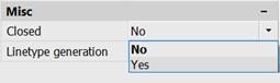
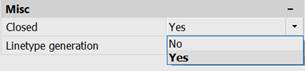
Close |
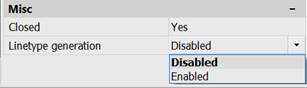
Closes a polyline – adds a segment between start and end vertices of a polyline. If the coordinates of the first and last vertices match, a zero-length segment will be added. You can also close a polyline using the Properties bar by setting the Closed parameter to Yes.
|
|
Open |
Opens a polyline – deletes a segment from start to end vertex. You can also open a polyline using the Properties bar by setting the Closed parameter to No.
|
|
Edit vertex |
Switches to the editing of vertexes mode (edited vertex is marked with “X” label). The option starts the following prompt in the command line: Enter a vertex editing option [Next/Previous/Break/Insert/Move/Regen/Straighten/ Tangent/Width/Exit/] <N> Options: Next - Goes to the next vertex. Previous- Goes to the previous vertex. Break- Breaks a polyline at the selected vertex. Insert- Adds a vertex in the specified place. Move- Changes the position of the selected vertex. Regen- Regenerates a polyline. Straighten- Changes a line segment to an arc segment. Tangent- Specifies the direction of the tangent in the selected vertex for further polyline fitting. Width- Specifies the first and second width of the segment, going after the selected vertex. Exit- Closes the editing of vertexes mode. |
|
Join |
Joins segments, arcs and polylines into one object – polyline. The option starts the following prompt in the command line: Select polyline or [?/End]: Option: End- Closes selection of objects. |
|
Width |
Specifies a new width for all polylines. |
|
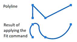
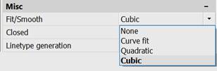
Fit |
Fits the polyline with arcs between polyline vertexes.
|
|
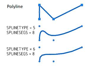
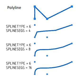
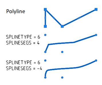
Spline |
Transforms a polyline into a spline which is an approximation of the source polyline between the start and end vertexes and is very similar to the source polyline. The result of a polyline transformation depends on the values of system variables: · SPLINETYPE – determines the smoothing type: quadratic (SPLINETYPE = 5) or cubic (SPLINETYPE = 6, default). · SPLINESEGS – specifies the number of segments in a curve. A higher value produces a smoother curve, but increases execution time. SPLINESEGS can be a non-zero integer from -32768 to 32767. By default, SPLINESEGS = 8. A positive value creates linear segments. A negative value of the variable means that arc smoothing will be applied (arcs are used as approximating segments), and the number of segments will be equal to the absolute value of the variable.
|
|
Decurve |
Returns a polyline to its original condition, cancels the results of the Fit or Spline commands. You can also disable smoothing and correct the smoothing type using the Properties bar.
|
|
Ltype gen |
Specifies a mode of the specified line type generation. The option starts the following prompt in the command line: Enter polyline linetype generator option [ON/OFF/] <Off>: If Off option is selected, generation of line type starts from dash and end dash in very vertex. If the value is On, generation will occur for the entire polyline (in this case, the distance between dashes or a dotted line may appear at the vertex). You can also enable or disable the linetype generation mode using the Properties bar.
|
|
Command options |
Description |
|
rEverse |
Changes the order of vertices to the opposite. The option is used to reverse the direction of objects that use linetypes with included text. For example, in accordance with the direction in which polyline was created, text for this linetype can be displayed inverted. |
|
Undo |
Cancels the last action of polyline editing. |
Command prompts when selecting a polyline:
|
Select polyline or [?/Multiple]: |
Select Multiple. |
|
Enter an option [Close/Edit vertex/Join/Width/Fit/ Spline/Decurve/Ltype gen/Undo]: |
Select the required option. Press Enter to finish the command. |
Command prompts to convert an object to a polyline:
|
Select polyline or [?/Multiple]: |
Select an object (line, arc, spline). |
|
Object selected is not a polyline. Do you want to turn it into one? [Yes/No/]<Y>: |
Press ENTER or select Yes option. If you need to undo the selection, specify No. |
|
Specify a tolerance <10>: |
When selecting a spline, enter the tolerance value to convert or press ENTER. |
|
Enter an option [Close/Edit_vertex/Join/Width/Fit/Spline/Decurve/Ltype_gen/Reverse/Undo]: |
Select an option necessary for editing. Upon completion of editing, press ENTER to end the command. |
Command prompts when selecting multiple objects:
|
Select polyline or [?/Multiple]: |
Select the Multiple option. |
|
Select objects [?/End]: |
Select objects. |
|
Select objects [?/End]: |
Select the End option. |
|
Convert Lines, Arcs and Splines to polylines? [yes/No] <Y>: |
Press ENTER or select Yes. If you need to undo the selection, specify No. |
|
Enter an option [Close/Edit_vertex/Join/Width/Fit/Spline/Decurve/Ltype_gen/Reverse/Undo]: |
Select an option necessary for editing. Upon completion of editing, press ENTER to end the command. |