
 De
De  Es
Es  Fr
Fr  Pt
Pt 

-
-
-
-
-
-
-
-
-
-
-
-
-
-
-
-
-
-
-
-
-
-
-
-
-
-
-
-
-
-
-
-
-
-
-
-
-
-
-
-
-
-
-
-
-
-
-
-
-
-
-
Wall
-
-
-
-
-
-
-
-
-
-
-
-
-
-
-
-
-
-
-
-
-
-
-
-
-
-
Wall
 Main menu: Construction - Architecture >
 Add Wall.
Ribbon: Construction - Architecture >Add Wall.
Toolbar: Architecture >Add Wall.
 Command line: SPWALLADD.
Walls can be straight and arc sections. To construct the arc wall segment in the context menu select the command arc.
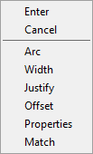
Ways of building arcs will be available in the context menu:
Arc - consistently indicates the starting, middle and end Points;
Bulge - consistently indicates the initial endpoint of the arc and the given bend;
Center - consistently indicates the arc center's starting and end points;
Segment - used for constructing rectilinear segments;
Justify - Consistently indicates left, center and right points;
Also in the context menu are the following options:
Axis - toggles for drawing the wall relative to its axis ( left, center, right);
Offset - - lets you draw a wall with an indent;
Properties - opens the properties dialog box wall;
Match - allows you to copy the properties being built with any existing walls.
Properties dialog wall
Dialog can be accessed from the context menu to create a wall, or by right-clicking on an already built facility.
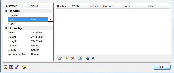
Key parameters are displayed in the left pane of the dialog box. In the right pane of the dialog box you can set the wall material. You have the opportunity to create a multi-layered wall.
All parameters of the walls can be set independently or choose Template. The template determines the composition of the wall, its width and height. If the user changes any of these parameters, then the connection is lost with the template.
 -
Wall material. Opens the material of the wall, where you can see and edit the list of available materials.
-
Wall material. Opens the material of the wall, where you can see and edit the list of available materials.
 -
New layer. Creates a new blank layer comprising the wall. Column Material selects the required material from the drop-down list. Priority layer will determine cleanup schedules while crossing the walls: a layer with a higher priority is displayed on top of layers with a lower priority.
-
New layer. Creates a new blank layer comprising the wall. Column Material selects the required material from the drop-down list. Priority layer will determine cleanup schedules while crossing the walls: a layer with a higher priority is displayed on top of layers with a lower priority.
 -
Delete Layer. Removes the layer from the wall.
-
Delete Layer. Removes the layer from the wall.
 -
Hatch . Allows you to set or change the shading layer.
-
Hatch . Allows you to set or change the shading layer.
 - Move Up. Moves the list of layers on the active layer above the line.
 -
Move Down. Moves the list of layers on the active layer below the line.
-
Move Down. Moves the list of layers on the active layer below the line.
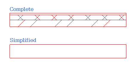
You can specify full or simplified representation. In the simplified representation layers and hatching are turned off.
Editing with grips
Central grip moves wall parallel to its original position.
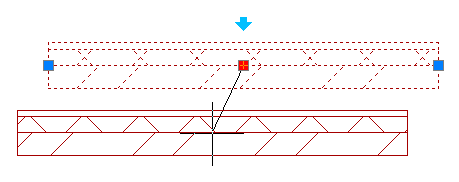
Recent handles allow the wall to turn.
Blue arrow allows you to turn the wall.