

 De
De  Es
Es  Fr
Fr  Pt
Pt 

-
-
-
-
-
-
-
-
-
-
-
-
-
-
-
Viewport Tools for Views Management
-
-
-
-
-
-
-
-
-
-
-
-
-
-
-
-
-
-
-
-
-
-
-
-
-
-
-
-
-
-
-
-
-
Viewport Tools for Views Management
Locator is a visual tool that can be used both in 2D model space and in 3D navigation, it allows you to:
· quickly identify the current orientation of a view (by the position of the orange marker point and the name of the view at the bottom of the locator);
· switch between orthographic, intermediate and isometric views (by clicking on the locator elements);
· set any arbitrary view (by clicking on the locator while holding down Ctrl key).
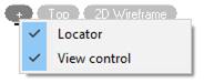
The display of Locator and View control tools on the screen is managed through the menu of  sign
sign
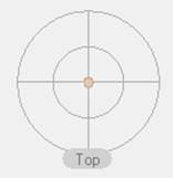
When opening a document or working with drawing elements, the Locator is inactive and shows the current position of the view with the dot mark  . The view name is translated in the tooltip below.
When you hover the cursor, the tool becomes active.
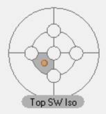
Each Locator element is responsible for setting a particular view.
The diagram below shows the location of vertices of orthographic views on the locator. Vertices are connected by edges of intermediate view. Zones of isometric views are located between these edges (light gray sectors in the diagram).
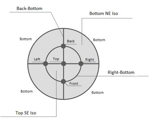
For example, knot circles serve to install orthogonal views, edges – intermediate views, and segments – isometric ones.
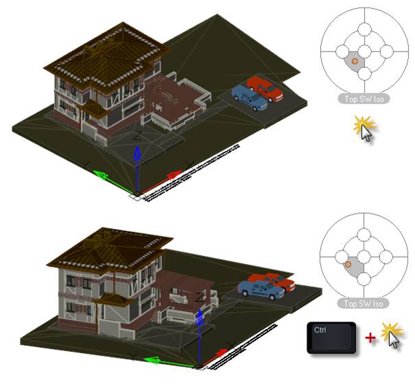
Setting an arbitrary view
In addition to the preset views, the locator allows you to set any desired view. To do this, click to select the desired position on the locator while holding down the Ctrl key. The orange marker  will be positioned exactly at the specified location, not just in the center of the locator zone. Below is the result of a normal click and click using Ctrl.
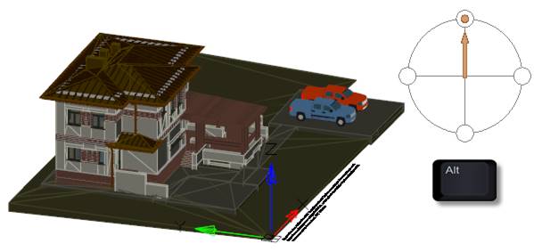
View rotation mode
When you hover the cursor over the locator with the Alt key pressed, it changes its appearance and switches to the view rotation mode. The mode allows you to rotate the current view around the axis of the viewing direction. In other words, it is possible to rotate the view clockwise or counterclockwise in the plane of the current view.
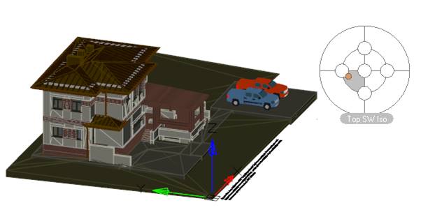
For example, an arbitrary view is displayed.
When you move the cursor over the locator and hold down the ALT, the locator will change its appearance.
Click on the locator while holding ALT will turn the view to the specified position. The arrow position indicates the current rotation position of the view.
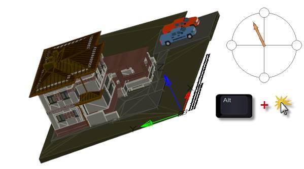
For accurate rotation for 90 degrees, click on one of the four circles on the locator edges.
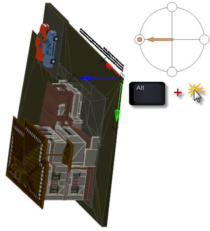
After releasing the ALT key, the locator will return to its normal state.
LOCATORDISPLAY, NAVVCUBEDISPLAY System Variables
The LOCATORDISPLAY and NAVVCUBEDISPLAY system variables control the display of the Locator tool in the current viewport when the current visual style is applied.
Acceptable values:
0 – the Locator is not displayed in 2D and 3D visual styles;
1 – the Locator is displayed in 3D visual styles, but not in 2D visual styles;
2 – the Locator is displayed in 2D visual styles, but not in 3D visual styles;
3 (default) – the Locator is displayed in 2D and 3D visual styles.
LOCATORLOCATION System Variable
The LOCATORLOCATION system variable determines the corner of the viewport in which the Locator tool is displayed: 0 (default) – upper right, 1 - upper left, 2 - lower left, 3 - lower right. In the current version, only the Locator is displayed in the upper right corner, regardless of the set value.
LOCATOROPACITY System Variable
The LOCATOROPACITY system variable controls the transparency of the inactive locator.
Default value: 50.
Acceptable values: from 0 to 100 percent. 0% - the ViewCube is not displayed in the viewport, except when the cursor is over the Locator location. Less than 100% - the Locator merges with the background of the drawing window and obscures objects underneath it to a lesser extent. 100% - the Locator is completely opaque in the drawing window and obscures all objects underneath it in the viewport.
The current version only supports 50% transparency, regardless of the set value.
LOCATORSIZE System Variable
The LOCATORSIZE system variable allows you to set the Locator size: 0 – small, 1 – normal, 2 – large, 3 – small, 4 (default) – automatic mode (the size increases or decreases depending on the size of the active viewport, the scale factor of the active layout, or the size of the drawing window).
The current version only supports the automatic mode, regardless of the set value.
LOCATORORIENT system variable
The LOCATORORIENT system variable allows you to control the mode to set the current (custom or default) view of model space.
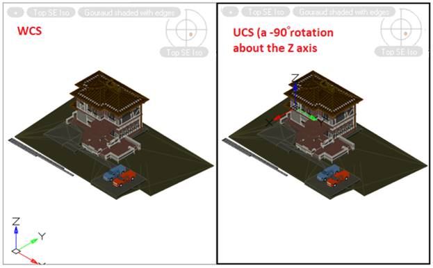
If the value of the system variable is 1 (UCS view orientation), then when you switch to the UCS, the view orientation changes in accordance with the direction of the axes of the current user coordinate system, which is reflected by the position of the locator marker (orange dot).
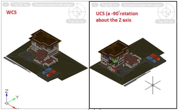
If the value of the system variable is 0 (corresponds to the orientation of the view according to the WCS), then when switching to the UCS, the orientation of the view will be determined relative to the world coordinate system.
The system variable only applies to setting custom views using the locator and from the context menu of the View Control widget.
The variable does not apply to setting views using the VIEW command, toolbars, calls from ribbon or menus.