
 De
De  Es
Es  Fr
Fr  Pt
Pt 

-
-
-
-
-
-
-
-
-
-
-
-
-
Vector Correction
-
-
-
-
-
-
-
-
-
-
-
-
-
-
-
-
-
-
-
-
-
-
-
-
-
-
-
-
-
-
-
-
-
-
-
-
-
-
-
-
-
-
Vector Correction
 nanoCAD button – Utilities >
  Vector Correction
Menu: File – Utilities > Vector Correction
 Command line: AUTOVC
The command allows you to correct geometric deviations made during construction or as a result of automatic and semi-automatic vectorization (tracing) for the following objects:
· line;
· polyline;
· arc;
· circle.
Objects for correction can be pre-selected or specified after launching the command.
Automatic correction allows you to:
· delete objects smaller than the specified size;
· restore contacts between objects;
· “paste” fragments into a single object;
· align lines along standard directions (UCS, Ortho-grid), if their deviations do not exceed the value specified by the user.
Vector correction parameters should be specified in the Properties (INSPECTOR) bar.
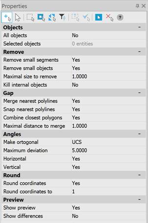
Parameters
|
Group |
Parameter |
Description |
|
Objects |
All objects |
Yes – all objects in the drawing participate in vector correction. No – vector correction is applied to selected objects. |
|
Selected objects |
Displays the number of selected objects. You can select objects in the drawing using the |
|
|
Remove |
Remove small segments |
Yes – removes redundant and overlapping segments by merging the polyline vertices. The size of the segment to be removed is specified in the Maximal size to remove field. The higher the value of the parameter, the more distant the vertices will be merged. For segments: when the Merge nearest polylines mode is enabled, the nearest segments are lengthened; when the Merge nearest polylines mode is disabled, the short segments are deleted. No – disables the mode. |
|
Remove small objects |
Yes – removes objects whose size is smaller than the value specified in the Maximal size to remove field. It is used to remove “garbage” in the drawing. No – disables the mode. |
|
|
Maximal size to remove |
The input field for the maximal size for removing segments and objects. The parameter value can be specified in the drawing by clicking the button to the right of the parameter. |
|
|
Kill internal objects |
Yes – removes vector objects located inside closed polylines (a closed contour of segments) and not intersecting with them. No – disables the mode. |
|
|
Gap |
Merge nearest polylines |
Yes – merges adjacent polylines into one, connecting their endpoints by a new segment. The distance between the combined polylines is specified in the Maximal distance to merge field. Does not merge segments into one, but extends them to fill the gaps for collinear ones and inserts intermediate segments for non-collinear ones. No – disables the mode. |
|
Snap nearest polylines |
Yes – combines adjacent polylines, changing their sizes and the position of segments so that the polylines have a matching vertex, but the objects are not combined. The distance between the combined polylines is specified in the Maximal distance to merge field. The mode is also applicable to segments. No – disables the mode. |
|
|
Combine closest polygons |
Yes – merges closed polylines (polygons) into one object if the distance between the polygons is less than the specified Maximal distance to merge parameter. No – disables the mode. |
|
|
Maximal distance to merge |
Input field for the maximal size to merge. The parameter value can be specified in the drawing by clicking the button to the right of the parameter. |
|
|
Angles |
Make orthogonal |
No – disables line alignment. UCS – enables line alignment by user coordinate system directions. Ortho Mesh – enables line alignment by the direction specified by the base angle and that orthogonal to it. |
|
Maximum deviation |
Input field for the maximum line deviation for applying line alignment. |
|
|
Horizontal |
Yes – aligns lines to the horizontal. No – disables the mode. |
|
|
Vertical |
Yes – aligns lines to the vertical. No – disables the mode. |
|
|
Angle auto estimating |
Yes – enables the automatic line correction mode by the ortho grid. No – disables the mode. |
|
|
Round |
Round coordinates |
Yes – rounds the coordinates of objects to the order specified in the Round coordinates to field. No – disables the mode. |
|
Round coordinates to |
The input field for the coordinate rounding order: 100000, 10000, 1000, 100, 10, 1, 0.1, 0.01, 0.001, 0.0001, 0.00001. |
|
|
Preview |
Show preview |
Yes – enables the preview mode for the specified vector correction parameters. No – disables the mode. |
|
Show differences |
Yes – enables the highlighting mode for objects to which vector correction modes are applicable.
Example of highlighting objects No – disables the mode. |
For vector correction:
1. Run the Vector correction command to correct all objects in the drawing or pre-select objects in the drawing and then run the Vector Correction command. If it is necessary to add objects to the selection, click the  button in the Selected objects line.
2. In the Properties bar, select the necessary correction options in the Remove, Gap, Angles groups.
3. Enable Yes options for the Show preview and Show differences options in the Preview group to track changes on the screen.
4. Select Yes in the command line to apply the correction.