
 De
De  Es
Es  Fr
Fr  Pt
Pt 

-
-
-
-
-
-
-
-
-
-
-
-
-
-
-
-
-
-
-
-
-
-
-
-
-
-
-
-
-
-
-
-
-
-
-
-
-
-
-
-
-
-
-
-
-
-
-
-
-
-
-
-
Use the links in the templates
-
-
-
-
-
-
-
-
-
-
-
-
-
-
-
-
-
-
Use the links in the templates
Stamps in the format template
Custom format may contain links to templates stamps available in the library. To add a stamp in the format used by the relevant rules.
Stamp Position and orientation when you insert a drawing format will be determined by the insertion point and orientation of text links:
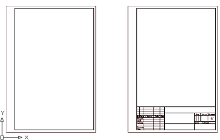
the figure shows the format template added referring to stamp basic inscription. When you insert a drawing format drawn stamp recorded in the library under the specified name.
the format can be added to any number of references to the stamps from the library.
Using text fields
In the pattern of the stamp may be used special signage text fields.
Text added to the template and starting with the single character "$", is recognized as a reference pointer on the field (the Count) input. In the input field of the dialog box, you can edit the stamp to record the text (for example, the name of the developer or check). Name field can contain characters of the Latin alphabet and the national or spaces. Dimensions of the input fields are defined primitives surrounding the insertion point, the reference index. If you found another symbol "$", the text after it considered the description field:
$Field_name [$field definitions].
the contents of the text box will be displayed in the list of object properties.
To limit the size of the input field or eliminate overlapping fields in the dialog, you can use the service line.
To create a stamp based on an existing base in the sample, the sample to be inserted into the drawing by setting in the dialog box "Stamp" mode "Display field names"  . After insertion into the drawing die can be used as the layout of the new stamp.
Standard fields stamps have a description in Russian (GOST), English (ISO) or German (DIN) language, the values of the fields available in the list of object properties.
| Name | Description | Contact with the properties of the document Inventor | Note: |
|---|---|---|---|
|
$Designation |
Description |
+ |
|
|
$DrawingName |
Name |
+ |
|
|
$Drawing type |
Drawing View |
|
|
|
$Material |
Material |
+ |
|
|
$Litera 1 |
Letter 1 |
|
|
|
$Litera 2 |
Letter 2 |
|
|
|
$Litera 3 |
Letter 3 |
|
|
|
$Mass |
Weight |
|
|
|
$DimScale |
Scale |
+ |
Sets the size of generated within the format |
|
$Sheet |
Sheet |
+ |
Changes in the automatic numbering |
|
$SheetCount |
Sheets |
+ |
Changes in the automatic numbering |
|
$Add.text |
Position the additional inspection |
|
|
|
$Author |
Developed |
+ |
|
|
$Control |
checked |
+ |
|
|
$TechControl |
Technical control |
+ |
|
|
$Add.subject |
Last additionally checked |
+ |
|
|
$NormControl |
the Regulatory Control |
+ |
|
|
$Approve |
Approved |
+ |
|
|
$Author (sign) |
Developer Signature |
|
|
|
$Control (sign) |
the signature checking |
|
|
|
$TechControl (sign) |
Signature of the technical control |
|
|
|
$Add.subject (sign) |
Signature additional inspection |
|
|
|
$NormControl (sign) |
Text regulatory control |
|
|
|
$Approve (sign) |
the signature approving |
|
|
|
$Author (date) |
the date of |
+ |
|
|
$Control (date) |
Date of Inspection |
+ |
|
|
$TechControl (date) |
Date engineering controls |
+ |
|
|
$Add.subject (date) |
Date further verification |
+ |
|
|
$NormControl (date) |
Date of regulatory control |
+ |
|
|
$Approve (date) |
Approval Date |
+ |
|
|
$Original # |
Part Number script |
|
|
|
$Sign & date 1 |
Signed and dated 1 |
|
|
|
$Instead # |
Instead, inventory number |
|
|
|
$Duplicate # |
Inventory number duplicate |
|
|
|
$Sign $date 2 |
Signed and dated 2 |
|
|
|
$Reference # |
the reference number |
+ |
|
|
$First use |
the primary use |
+ |
|
|
$Format |
Format |
+ |
|
|
$Enterprise |
Enterprise |
+ |
|
In the pattern of the stamp can be used table nanoCAD Mechanica. Included in the stamp table when you insert a drawing can be edited as regular tables nanoCAD Mechanica (except that the die table can not be modified in the editing mode screen).
Additional features
Converting from a previous version - The settings.xml file defines the correspondences of field names for the formats of old and new versions. If the enterprise used custom stamps of previous versions, the names of their fields can be added to the corresponding section of this file.
Settings.xml is located in the folder:
x64 - %PROGRAMDATA%\Nanosoft AS\nanoCAD x64 25\NanoMechanical\DataRO\en-US\settings.xml
Integration with other objects
Tables - Format allows you to use tables as stamps. This preserves virtually all the functionality built-in table.
Universal marker - The values of any fields format can be used in a universal marker.
Dimensions - When you create within the format size, the size takes out set in the title block of the format.
Legend roughness - The format may be associated with the designation of a roughness surfaces unspecified. Icon roughness is automatically transferred to the upper right corner of the format.
Property document - The value of the standard field format is synchronized with the attributes of the file in which it was created.
Technical conditions - Format calculates the coordinates of the columns to accommodate the technical requirements.
Attribute documents TechnologiCS - Exchange values between the fields and the format of the document attributes. You can set the matching fields automatically (by the same name), and then specify manually. Establishing appropriate stored for later use.
Zone format - The format can be calculated, is there any point in it. If so, you can receive the designation area containing the point.