
 De
De  Es
Es  Fr
Fr  Pt
Pt 

-
-
-
-
-
-
-
-
-
-
-
-
-
-
-
-
-
-
-
-
-
-
-
-
-
-
-
-
-
-
-
-
-
-
-
-
-
-
-
-
-
-
-
-
-
-
-
-
-
-
-
-
-
-
-
-
-
-
-
-
-
-
-
-
-
-
-
-
-
-
-
-
-
Universal marker
-
-
-
-
Universal marker
 Main menu: Construction - Library objects - Marks and groups >
 Add marker.
Ribbon: Construction - Library objects >Add marker.
Toolbar: "Library objects">Add marker.
 Command line: SPCREATEUMARKER.
The "Marker" tool is designed specifically to create a connection between an arbitrary graphic object (primitive) nanoCAD and a spreadsheet-specification. A universal marker is a translator of data from drawing objects into the nanoCAD Construction table by means of special means - marker attributes.
Marker attributes can be visible or hidden. The values of the visible attributes are displayed in the drawing as text strings.
The marker, as an object nanoCAD Construction , can be saved in the object library and used repeatedly. The marker can also be included in the groups of objects nanoCAD Construction , providing the ability to specify the entire functional groups.
Create marker
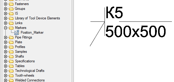
Let's consider creating a marker in the form of a positional leader.
-
Set the required current scale.
-
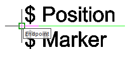
Insert two text lines into the drawing and draw a horizontal line between them.

These objects will form a leader shelf template with two text labels. To use text strings as marker attributes, the first character must be "$".
-
Call the command
"Add marker", use a box or crossing box to select the objects that made up the marker.
-
Snap the base point of the marker.
-
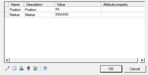
The "Creation of a marker" dialog box appears. The properties table will list the attributes entered in the callout text boxes:
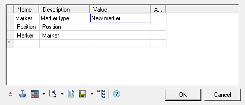
Column "Name" contains the working name of the attribute.
Column "Description" describes the attribute.
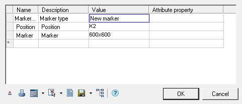
In column "Value" the values of the attribute are entered. Values can be either numeric or text. Auxiliary commands are available in the context menu of the "Value" column.
Column "Attribute property" is used to indicate the type of the input attribute. Various attribute labels are provided to indicate their type. The default is "Set to simple field".
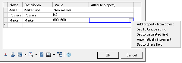
Attribute types:
-
Add property from object - allows you to set an attribute value by associating it with the attribute value of another object in the drawing.
Important! An object is understood as an object from the base of standard products. After choosing the type, it is suggested to select the object and the object attribute.
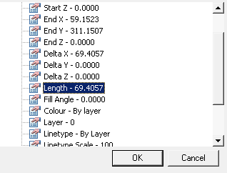
After selecting an attribute, its value falls into the "Value" column, and in the "Attribute property" column the name of the selected attribute.
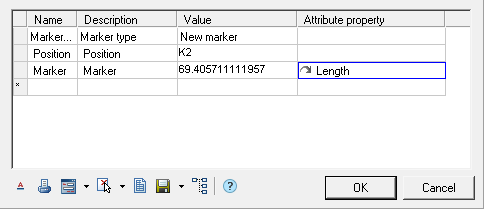
After assigning an attribute, you can change the type of relationship with an object attribute:
 One-way communication - changing the value in an attribute of an object affects the value of the marker.
 Two way communication - changing the value in the marker affects the attribute of the object, and vice versa.
 Basic communication - an attribute of an object can only be changed from a marker. If the attribute is a table value in a basic relationship, the closest value from the table is displayed. The entered value will be displayed in brackets.
 -
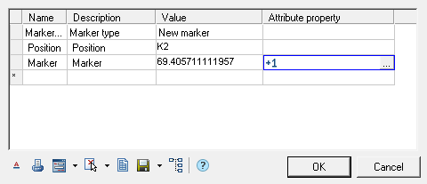
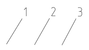
Set To Unique string - allows you to set a counter attribute that will increase its value by 1 for each subsequent inserted marker. In the "Value" column for the visible counter attribute, you can specify a character string - a prefix. In the drawing, the counter value will be appended to the prefix.
-
Set to calculated field - allows you to set the value of an attribute using a mathematical expression, using references to other marker attributes, operators, and mathematical functions. The name of the desired attribute is used as a reference to another marker attribute.
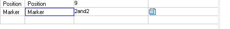
Note: Computed attributes are defined and calculated from top to bottom. Important! Calculations are performed in curly braces. Function:
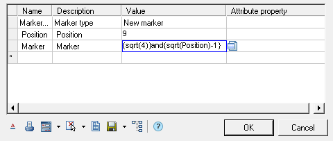
Result:
-
Automatically increment - allows you to set a counter attribute that will increase its value by 1 compared to the same attribute of the previous inserted marker. Such a counter attribute allows repetition of the same values for several markers, which distinguishes it from an attribute set to a unique value.
-
Set to simple field - sets the default attribute type to plain text.
Note: Attributes included in the block can be included in the marker attribute table nanoCAD! -
-
Edit the marker using the marker controls at the bottom of the dialog box.
Include:
-
"Marker draw mode". When you click on this button, a drop-down list of rendering modes appears:
-
 Simple marker.
 -
 Draw position line.
 -
 Linear align.
When you select the display method with the addition of a leader line, an additional button
 "Arrow Type" appears to select the type of arrow:
Click this button and select the desired extension line arrow type.
Arrow display parameters are defined in the "Settings - Symbols - Extension - Additional extension lines" settings.
-
-
 "Unploted". When this button is enabled, the marker is placed on a special layer that is not displayed when printing. When this mode is activated, the icon on the (
 ) button changes and the marker is displayed in gray on the screen (in accordance with the color of the non-printed layer).
 -
 "Show form editor"- calls the custom form editor to create a dialog for working with marker attributes.
The following commands are available in the drop-down menu:
"Edit Form". Open Form Editor.
"Add Form. Adds additional forms, while the marker can change the appearance of the form, by condition or by the user's choice. By default, the marker has one form.
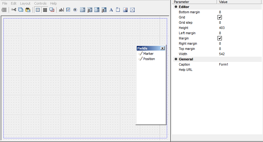
The form editor uses standard Windows form generation technology. The toolkit consists of three blocks - the graphic editor area, the toolbar with form objects and the properties window of the inserted elements. For inserted fields, the "Field Name" ("Variable") can be selected from the list of existing marker description fields. In this case, the default field value is equal to the field value in the marker description.
When adding a second form, you are prompted to enter a name for the form. The variable Tag - mcFormName is added to the properties table. This variable is responsible for the name of the form, it can be set in a calculated field and, for example, made equal to execution. Empty or "Main" is considered the main form.
-
 "Geometry". Used to change the appearance of the generic marker and define the insertion point.
The following commands are available in the drop-down menu:
Get new geometry. The button is used to change the appearance of the universal marker and define the insertion point.
Export marker source graphics. Exports marker geometry to a file.
Add Implemetnation. Adds additional performances, while the marker can change its appearance, by condition or by the user's choice.
When creating a new implementation, you are prompted to enter its name. When adding implementation, the Tag - mcImplementation variable is added to the properties table. This variable is responsible for the name of the current marker implementation. It can be set to a calculated field or linked to a list on a form. Empty or "Main" is considered the main implementation.
-
 "Set parameters table". Opens the marker parameter table editor. When inserting a marker and having a table of values, it is possible to assign a group of values to the marker attributes.
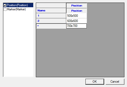
In the list, select the parameters whose values will be selected from the table. In the right part of the window, enter the required number of lines with values. Close the dialog with the "OK" button.
-
 Save changes to odatabase. The button is intended for writing a marker to library nanoCAD Construction .
 -
 Apply changes to all markers of this types. Applies changes to all markers of this type in the drawing. Serves for changing the marker template for all markers made according to this template and inserted into the drawing.
-
-
If necessary, add any number of hidden attributes, filling in the rows of the table in sequence. The attribute is added in the bottom line of the table, marked with an "*" symbol.
-
For future use of the marker, save it to the database as a named object.
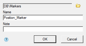
In the "Create element" dialog box, specify the path to save, the name of the object and the note (for more information on working with the object base, see the nanoCAD Construction 25 Object Manager). After you save the marker, a message appears prompting you to update the existing copies of the marker in the drawing.
-
nanoCAD Construction makes it possible to immediately apply the created marker. The command line prompts you to install the generated token. Pick an insertion point in the drawing. Identical markers can be simply copied in the future. In other cases, the marker is inserted directly from the base.
Edit marker
Editing of a marker is carried out in a dialog box, the title of which corresponds to the name of the marker. For example, when you call for editing the "Position_Marker" marker, the creation of which was described in the previous paragraph, the dialog box will look like this:
Additional commands are located at the bottom of the window:
-
"Marker draw mode". When you click on this button, a drop-down list of rendering modes appears:
-
Simple marker.
-
Draw position line.
-
Linear align.
When you select the display method with the addition of a leader line, an additional button
"Arrow Type" appears to select the type of arrow:
Click this button and select the desired extension line arrow type.
Arrow display parameters are defined in the "Settings - Symbols - Extension - Additional extension lines" settings.
-
-
"Unploted". When this button is enabled, the marker is placed on a special layer that is not displayed when printing. When this mode is activated, the icon on the () button changes and the marker is displayed in gray on the screen (in accordance with the color of the non-printed layer).
-
 "Highlight info source object". Highlights in the drawing the object with which the marker is associated (The function is available if the "Add property from object" mode is set for one or several attributes and the corresponding object was specified when inserting the marker).
 -
 "Edit marker properties". Turns on the edit mode, in which you can change the appearance of the marker, add or remove attributes.
System variables in marker
mcImplementation - Execution management. Empty or "Main" means the main view.
mcFormName - Form management. Empty or "Main" means the main form.
mcArrowSize - Arrow size control.
mcDefLayer - Controls the marker location layer. The "Value" field contains the name of the layer.
mcShowFormOnInsert - Controls the display of the dialog when inserting. If the value is 0, the dialog is not shown when inserting. The value can be calculated.