De
De  Es
Es  Fr
Fr  Pt
Pt 

-
-
-
-
-
-
-
-
-
-
-
-
-
-
-
-
-
-
-
-
-
-
-
-
-
-
-
-
-
-
-
-
-
-
-
-
-
-
-
-
-
-
-
-
-
-
-
-
-
-
-
-
-
-
-
-
-
-
-
-
-
-
-
-
-
-
-
-
-
-
-
Threaded fastening
-
-
-
-
-
-
-
-
Threaded fastening
 Main menu: Construction - Library objects >
 Threaded fastening.
Ribbon: Construction - Library objects >Threaded fastening.
Toolbar: "Library objects">Threaded fastening.
 Command line: SPJOINT.
Tool for inserting a threaded fastening from library nanoCAD Construction .
Procedure
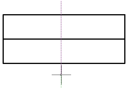
1. Specify the starting point of the threaded fastener in the drawing.
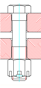
2. Specify the end point of the threaded fastener, the "Fasteners" dialog will open. When inserting, tools are available to select the direction of drawing. Specifying the start and end points defines the centerline of the fastener. The intersected lines make up the thickness of the part package being fastened.
3. In the "Fasteners" dialog box, customize the look of the threaded fastener.
| Note: | The thread fastener insert dialog automatically saves the last selected template and thread diameter. |
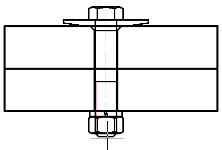
4. Confirm the settings with the "Apply" button, or with the "OK" button if you want to close the dialog at the same time. A threaded fastener will be built.
Editing a threaded fastener
You can edit a threaded fastener by editing the "Threaded fastener" object, or by editing individual parts included in the threaded fastener.
When editing, you can change the composition, diameter of the threaded fastener, as well as the parameters of the individual parts that are included in it.
To open the threaded fastener setup dialog, apply any of the standard editing tools to the centerline of a group of parts.
If tooltips are enabled in nanoCAD Construction settings, then when you hover the cursor over the centerline, the "Threaded fastening" tooltip appears.
Threaded fastener settings dialog box
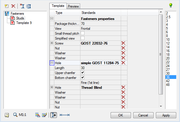
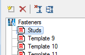
Template list panel
It is possible to save a threaded fastener template for later reuse of assemblies with the same set of parts. To work with templates, use the buttons at the top of the dialog box, and below is a list of available templates:
Button  "Create new template" adds a new empty template. When creating a new template, the required number of holes is automatically added depending on the number of lines crossed in the drawing.
Button  "Delete template" removes the selected template from the list. "Editing template" stores the current setting of the threaded fasteners. It cannot be removed.
Button
 "Selecting insertion point" is intended to reselect the insertion point and the length of the threaded fastener in the drawing.
Button  "Manually select holes length and placement" opens a window for setting parameters of a package of connected parts.
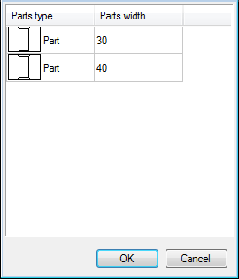
LMB clicking on one of the cells in the "Parts type" column switches the part / gap:
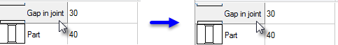
In the "Parts width" column, the thickness of the corresponding part (or gap) is set. After setting the parameters of the connection package, close the window with the "OK" button.
The context menu of the list of templates contains the commands:
- Add folder
- Delete object
- Rename
- Import object
- Export object
- Send by email
- Copy
- Configuration tool
These commands are similar to those used in the object manager nanoCAD Construction .
Tab "Template"
The following settings are available on the "Template" tab in the center of the dialog:
-
Fasteners properties
- Package thickness - thickness of the package of parts to be joined, in mm.
- View - selection of standard image projection.
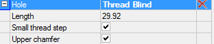
- Small thread pitch - fine pitch switch.
- Simplified view - simplified / full image switch.
-
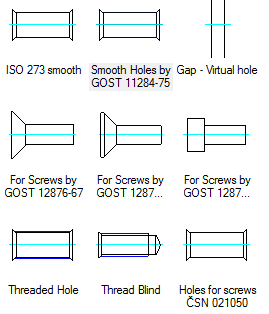
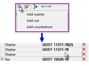
Details of the threaded assembly. The components included in the assembly are listed here in order.
- Screw
- Hole
- Spot facing
- Washer
- Nut
To select a part of a threaded assembly from the nanoCAD Construction base, click in the cell of the GOST column of the corresponding element.
The "Select object" dialog box will open the attachment parts folder.
Additional settings for assembly components are available when expanding the list:
Button "Clear" in the right column of the list table clears the selected position.
Tab "Preview"
A preview of the threaded assembly is available on the tab.
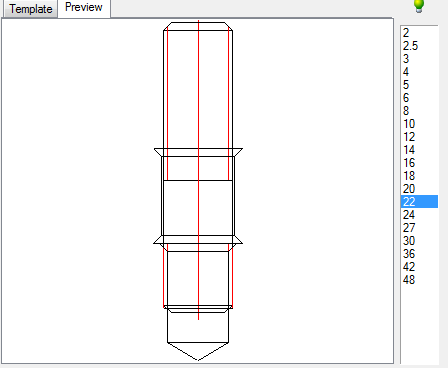
List of thread diameters

|
The "lightbulb" icon above the list indicates that the selected diameter value can be used for all objects in the assembly:
|
 The diameter value does not match one or more parts. Assembly is not possible.
 The diameter value applies to all parts in the assembly. Assembly is possible.
Button  "Add part to template"
Adds a part to the assembly after being selected from the list. The list of details available for adding depends on the currently selected object:
Button  "Remove part from template"
Removes the selected object from the parts list.
Button  "Dynamic selection"
Turns on the mode of visual selection of the bolt length after closing the dialog.
Graphical display type selection list
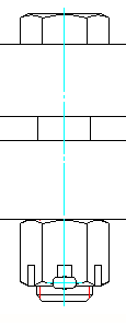
When inserting a threaded fastener, 3 display methods are available, selected by the "Select fasteners insert part" button on the bottom toolbar of the dialog. The figure on the button displays the currently selected display method:
|
With local out |
Normal insert type |
Insert hidden fastener |
|---|---|---|
|
|
|


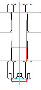
Displaying chamfers on holes
To select the options for displaying chamfers in the drawing, you must correctly place the marks in the hole properties.
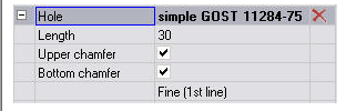
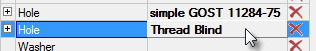
Setting the hole type
To change the hole type, click on it in the connection part set and select a different type in the "Select object" dialog box that opens.