

 De
De  Es
Es  Fr
Fr  Pt
Pt 

Tables
 Main menu: Mechanical - Tables >
 Tables.
Ribbon: Mechanical - Symbols >Tables.
Toolbar: Tables (on toolbar "Tables").
 Command line: MCTABLE.
Causes dialog box to insert a new table.
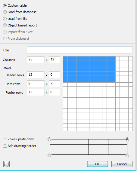
- To create a custom table, select Custom. In input fields specify the dimensions of the created table, or on the layout, drag the mouse to the right as many rows and cells as required. When subsequent editing the number of rows, columns, cell sizes can be changed.
- To insert a standard table, select load from database. You can insert a standard table of the base elements Building site . In the dialog box, select the table you want. Database elements Building site is available for all major types of standard tables.
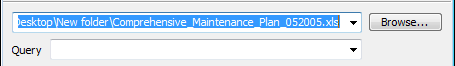
- To insert a table from a file, select Load from file.
Click Browse and select the file table.
Supported formats:- tbl - tables files
- dat - data file or a text file
- mdb - database Microsoft Access
- xls - Spreadsheet Microsoft Office Excel
- xlsx - spreadsheet Microsoft Office Excel 2007
- csv - table cell separated by commas
- txt - standard text file
- xml - XML document
- odf - OpenDocument Format.
When loading a table of xlsx, xls file, you must select the Excel document sheet.
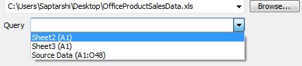
Important! Select the sheet can be made after a table is loaded from the file. 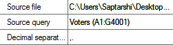
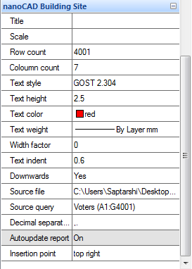
In the properties of a table row source file displays the path to the source file of the table.
Select line Request to enter the desired page of the document. Then in the Table Editor, click
 Update Table from an external source.
When loading a table from a file mdb drop-down list displays a list of database query.
Note: To import tables from files, you can drag a file from Explorer to the dialog table .
When you drag a file from Windows Explorer in the imported table is added to the existing table.
When you drag a file from Windows Explorer dialog box replaces the existing table to be imported.
- To generate a report based on a sample of objects, select the objects in the sample report.
-
To make a selection of items, click Select.
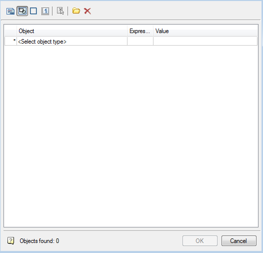
The search conditions are set in the Quick selection dialog.
Further dialogue is given based on what the attributes are and creates a report on the selected objects.
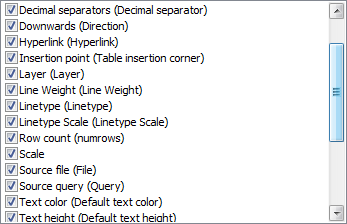
Includ attributes for the report in the list by selecting flags
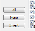
- All- selects all attributes
- None - the choice is removed from all the attributes
- Invert - inverted selection attributes
The table is created with a template report form
=Iff(Exist(Object."Autoreport");Object."Autoreport";"")
This formula checks whether there is a line for the attribute named Autoreport, and displays its value in a cell. Otherwise, leave the cell blank.
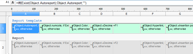
The number of columns in the table determined by the number of selected attributes.
- To import a table from Excel, select Import from Excel. To activate this item, the document should be opened.
- Select the insertion point of the table.
-
- Select the numbering of rows in the table.
-
If the switch rows upside down is enabled, the line numbered in reverse order.
- When the checkbox
 after you insert the table will start a dialogue format.
 - Click OK and the insertion point on the drawing table.
| Note: | If the drawing pre-select a group of objects, and then run the tables,
you will be prompted to create a report based on a sample of objects. |