De
De  Es
Es  Fr
Fr  Pt
Pt 

-
-
-
-
-
-
-
-
-
-
-
-
-
-
-
-
-
-
-
-
-
-
-
-
-
-
-
-
-
-
-
-
-
-
-
-
-
-
-
-
-
-
-
-
-
-
-
-
-
-
-
-
-
-
-
-
-
-
-
-
-
-
-
-
-
-
Symmetrical rectangle
-
-
-
-
-
-
-
-
-
-
-
-
-
Symmetrical rectangle
 Main menu: Construction -Architecture - Graphics >
 Symmetrical rectangle.
Ribbon: Construction - Architecture >Symmetrical rectangle.
 Command line: SPRECT.
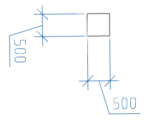
The command allows you to insert axisymmetric rectangles into the drawing, which are closed polylines.
Procedure
1. Call the "Symmetrical rectangle" command. The "Axisymmetric rectangle" dialog opens.
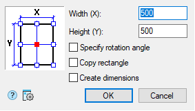
2. In the "Axisymmetric rectangle" dialog box, specify the required dimensions for the rectangle.
3. Specify the insertion point in the graphic field of the dialog box (on the left) (the current insertion point is marked with a red square).
4. Set the modes if necessary:
"Specify rotation angle" - when inserting a rectangle, it will be possible to rotate the rectangle relative to the insertion point;
"Copy rectangle" - after inserting a rectangle, it is proposed to insert copies of it;
"Create dimensions" - sets the overall dimensions of the rectangle.
5. Confirm the changes with the "OK" button.
6. Place the rectangles on the drawing. Placement of rectangles on the drawing is done cyclically. To complete the command, press the "Enter" key.