
 De
De  Es
Es  Fr
Fr  Pt
Pt 

-
-
-
-
-
-
-
-
-
-
-
-
-
-
-
-
-
-
-
-
-
-
-
-
-
-
-
-
-
-
-
-
-
-
-
-
-
-
-
-
-
-
-
-
-
-
-
-
-
-
-
-
-
-
-
-
-
-
Suppression contour
-
-
-
-
-
-
-
-
-
Suppression contour
 Main menu: Mechanical - Standard parts - MechWizard >
 Supression contour.
Ribbon: MechWizard - MechWizard >Supression contour.
Toolbar: Suppression contour.
 Command line: MCWIZCONTOUR.
| Important! |
The command prepares the sketch for recognizing the execution type of the base object. |
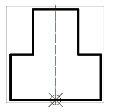
A suppression contour limits the area that the object overlaps with other graphics in the drawing. If the suppression contour is not specified, it is created automatically when the model is recognized by the external outlines of the part, and service objects are not taken into account.
Procedure
1. Draw a closed polyline on the sketch that matches the shape and size of the required suppression contour (in the figure, a rectangle around the sketch).
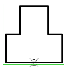
2. Call the command "Supression contour".
3. Specify the constructed polyline. The contour is highlighted in green in the sketch.
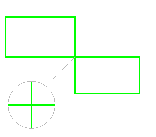
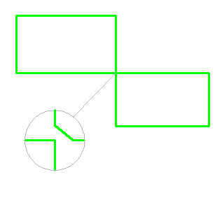
A prerequisite for the contour is the absence of self-intersections. To avoid self-intersections for a compound contour, create the contour manually, leaving a minimum "isthmus" between the areas:
| Wrong | Right |
|---|---|
|
|
If the suppression contour cannot be created automatically (the outer boundaries of the object do not form a closed contour), then when the object is inserted into the drawing, a corresponding warning message will be displayed. However, errors in the suppression contour do not affect the applicability of the recognized object, and can only appear in the wrong overlap of other objects in the drawing.