
 De
De  Es
Es  Fr
Fr  Pt
Pt 

-
-
-
-
-
-
-
-
-
-
-
-
-
-
-
-
-
-
-
-
-
-
-
-
-
-
-
-
-
-
-
-
-
-
-
-
-
-
-
-
-
-
-
-
-
-
-
-
-
-
Strength calculation of spur gearing
-
-
-
-
-
-
-
-
-
-
-
-
-
-
-
Strength calculation of spur gearing
 Library: Calculations - Spur gears- Strength calculation of spur gearing
Operation of the second embodiment does not use calculators for design, but only for testing the strength of the transmission to the known or predetermined geometrical parameters.
Checking calculations has its own form of the report and data input. In all other respects similar to the method described above.
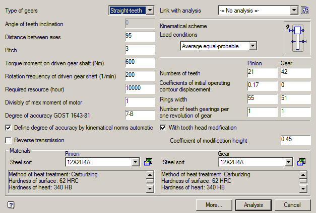
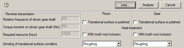
By clicking on the button "More ..." open additional field data input for the reverse gear, the method of machining the tooth flank and its heat treatment.
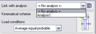
From this window, click on the icon  You can go to the Calculation wizard. If any payments were previously carried out, their results can be accessed using the drop down menu.
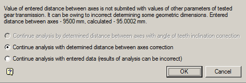
If the entered spacing does not match the entered calculation parameters, then when it changes you will receive a message which will be offered options:
-
Continue with the correction of the calculation specified center distance
-
Continue with the entered payment data (calculation results may be incorrect)
Initial data
Type of gears
The drop-down list of the gear types allows you to select one of three options: spur, helical, herringbone or wheel:

Angle of teeth inclination
When choosing a helical or herringbone wheels in the "angle of the teeth" should enter a value in degrees of the desired angle of inclination of the tooth line in the recommended range (typically 8-22 ° for helical and 25-40 ° for chevron wheels).
If this field is left blank, the program installs by default a certain angle, which lies within the specified limits. Most often, this angle imposed by the previous calculation. It can be changed either directly or by subsequent adjustment calculation.
Distance between axes
Pitch
Rotation frequency of driven gear shaft (1/min)
The field is filled in accordance with the terms of reference and the expected characteristics of the engine.
Torque moment of driven gear shaft (Nm)
The field is filled in accordance with the terms of reference and the expected characteristics of the engine.
Required resource (hour)
The field is filled in accordance with the terms of reference and the expected characteristics of the engine.
Divisibly of max moment of motor
The field is filled in accordance with the terms of reference and the expected characteristics of the engine.
Degree of accuracy GOST 1643-81
Kinematical scheme
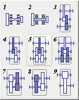
The two-stage and three-stage gear units can be run on deployed or coaxial. In simple circuits deployed, each stage consists of a pair of gears. The disadvantage of such schemes - an uneven load distribution between the bearings, so that the resulting deformation of shafts occurs the load concentration along the length of the tooth, causing the need for a shaft with high rigidity.
This disadvantage is eliminated by using bifurcated stages. Preferably in the two-stage gear as forked use a high-speed, and in the three-stage - the intermediate stage.
The large width of a low-speed stage in these cases does not cause a significant load concentration along the length of the tooth due to the symmetrical arrangement of gears with respect to the supports.
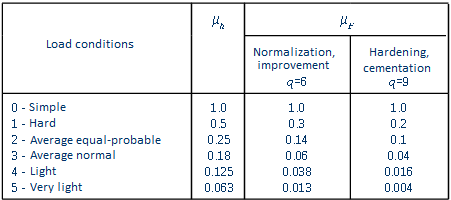
Load conditions
Load conditions is selected from the dropdown list.
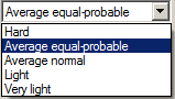
Table of values of equivalence ratios for each loading mode:
Group "Materials"
Materials of gears and their characteristics are selected from a drop down list or from the database.
 Go to the database by clicking on the appropriate button to the right of the selection grade of steel.
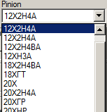
Type of material selection group gears and wheels:
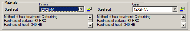
For convenience, you can select to see comments to the selected material.
Group "Reverce transmission"
The group contains the following fields:
- Rotation frequenct of driven gear shaft
- Torque moment of driven gear shaft (Nm)
- Required resource (hour)
Check "Transitional surface is polished"
Check "With tooth root inclusion"
Grinding of transitional surface conditins
Activity fields depends on the chosen material
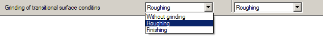
If the transition is made grinding surface of the teeth, the required grinding mode can be selected from the corresponding drop-down list.