De
De  Es
Es  Fr
Fr  Pt
Pt 

-
-
-
-
-
-
-
-
-
-
-
-
-
-
-
-
-
-
-
-
-
-
-
-
-
-
-
-
-
-
-
-
-
-
-
-
-
-
-
-
-
-
-
-
-
-
-
-
Stationing
-
-
-
-
-
-
-
-
-
-
-
-
-
-
-
-
-
-
-
-
-
-
-
-
-
-
-
-
-
Stationing
 Main menu: Construction - Symbols -
  Stationing.
Ribbon: Construction - Symbols - Stationing.
Toolbar: Construction symbols - Stationing.
 Command line: SPSTATIONING.
Procedure
1. Call a command "Stationing". The "Stationing" dialog will open.
2. In the "Stationing" dialog box, set the parameters of the station and confirm the settings with the "OK" button.
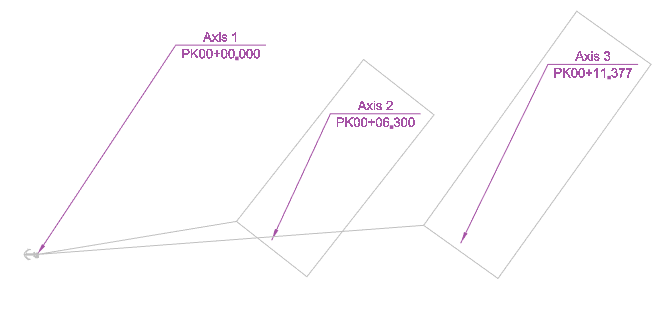
3. Insert the first anchor leader or specify the polyline on which the stationing will be placed. When specifying a polyline, the first anchor leader will be set to the starting point of the polyline. The first designation of the station is the anchor, the report goes from it and the subsequent inserted station is connected with it.
4. Position the text of the first mark.
5. Insert the desired number of marks. If a polyline was specified, the leader arrow will be associated with the polyline. To finish inserting station symbols, press the "Enter" key.
Edit
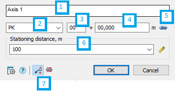
The edit dialog contains:
1. Text input field above the shelf.
2. Drop-down list of picket designation (mileage): PK or KM.
3. The field for the number of the initial station.
4. The field of the value of the distance of the initial station.
5. Button  "Associative" - allows you to link a new mark to existing marks. After binding, all fields except the text above the shelf will not be editable.
6. Drop-down list "Stationing distance, m" - sets the distance between pickets. The value is selected from the list, entered manually or taken from the drawing. To specify a value from a drawing, use the  "Measure" command.
7. Switch for selecting the type of mark:  "Positional mark" or
  "Linear mark".
Grips
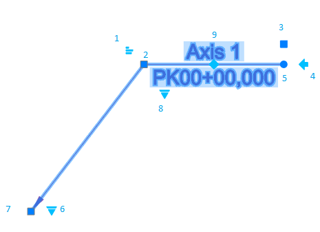
1. Text alignment knob above the shelf.
2. Handle for moving the shelf.
3. Text stretch/shrink handle.
4. Handle for changing the direction of the shelf location.
5. Handle for turning the shelf.
6. Handle for changing the view: PK or KM.
7. Moving the arrow.
8. Selecting the type of GCP naming.
9. Choice of base mark.
Double-clicking on the anchor on the first mark displays associative links.