-
-
-
-
-
-
-
-
-
-
-
-
-
-
-
-
-
-
-
-
-
-
-
-
-
-
-
Show Boundary
-
-
-
-
-
-
-
-
-
-
-
-
-
-
-
-
-
-
-
-
-
-
-
-
-
Show Boundary
This option shows a set of raster images, blocks or external references in the enclosed area. (see “Set show boundary for a viewport” section).
The show boundary defines the visibility of objects in the current document. The original objects are not changed.
Setting of the clip boundary is achieved using the clipping contour.
Clipped blocks or external references, raster images and viewports can be edited as well as unclipped ones.
Tools to work with boundaries are located:
on the Insert ribbon tab in the Reference section:

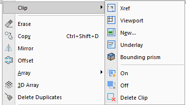
and in the menu: Modify – Clip:

 Ribbon: Insert – Reference – Show Clip
 Menu: Modify – Clip
|
|
Show Clip ON Displays the clipped insertion fragment. |
|
|
Show Clip OFF Displays a full insertion. |
The form and size of clip contour can be changed using grips located in the contour vertices.
Commands to manage the display of clip borders:
 Ribbon: Insert – Reference – Borders >
|
|
Show but not Print Borders |
|
|
Show and Print Borders |
|
|
Hide Contours |


 De
De  Es
Es  Fr
Fr  Pt
Pt 


