-
-
-
-
-
-
-
-
-
-
-
-
-
-
Settings of Raster Snap
-
-
-
-
-
-
-
-
-
-
-
-
-
-
-
-
-
-
-
-
-
-
-
-
-
-
-
-
-
-
-
-
-
-
-
-
Settings of Raster Snap
 Menu: Tools – Drafting Settings > Object snap tab >
  button
 Status bar: context menu of
  >
>  Setup raster snap
 Command line: R2VSNAPSETUP
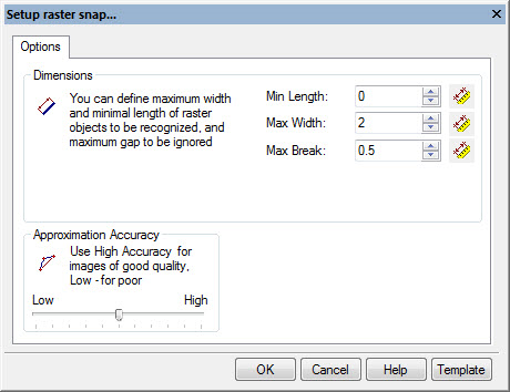
Raster snap have to be setup to help program to recognize types of raster objects (lines, arcs, circles) correctly.
Snap operations are based on recognizing algorithms for raster objects. The program calculates a vector object, ideally approximating raster lines, which are close to mouse pickbox and offers to snap to characteristic points of the object. The efficiency of raster snap highly depends on parameters, specified in the Raster Snap Settings.
To specify settings for a raster snap:
1. Open Raster Snap dialog from context menu or by  button near Raster on Object Snap tab from Drafting Settings dialog.
2. Set raster snap settings in accordance with your raster image characteristics:

Settings:
|
Min Length: |
This parameter defines the minimum size of a raster object that can be recognized. To set Min Length: • Click or • Enter value to the field. |
|
Max Width: |
This parameter defines the maximum width of raster lines that can be approximated by lines, arcs, circles, and polylines. If the width of a raster line exceeds Max Width value, then the only possible recognition mode is Auto tracing and approximating with an outline object. To set Max Width: • Click or • Enter value to the field. It’s better to set this value a little more than maximum width of the thickest line in the image. |
|
Max Break: |
Sets the length of the maximum ignored breaking raster lines. If a raster line is broken into parts it should be traced as an entire object, then the value of Max Break should be set to the largest gap between the raster line parts. The program will ignore the breaks and create single vector object, approximating the whole raster line. By setting a comparatively large value of the parameter, users can, for example, trace dash-dotted raster lines, and arcs as single entities. To set Max Break: • Click or • Enter value to the field. |
|
Accuracy |
This parameter determines the accuracy of approximation of the original raster object with a vector one. If the original image is distorted (for example, circles have the form of ellipses), then reduce the value of the Approximation Accuracy parameter. However, this leads to inaccuracies in recognition, for example the program might take a short arc for a line. When the quality of a raster image is high, increase the value of the Approximation Accuracy parameter. Sometimes before tracing the quality of the raster image can be improved by application of a smoothing filter. To set Approximation Accuracy: • Move slider. If the original raster entities are distorted (for example, raster circles have an elliptical shape), recognition accuracy will increase when moving the slider to the left, to the Min value. If the original raster image is of good quality, the slider should be moved to the right, to the Max value. |
3. When ready – click OK button.


 De
De  Es
Es  Fr
Fr  Pt
Pt 

 button and specify distance (2 points on raster line) that should be recognized as line.