
 De
De  Es
Es  Fr
Fr  Pt
Pt 

Set Parameter
 Main menu: Construction - Library objects - MechWizard >
 Set Parameter.
Ribbon: Construction - MechWizard >Set Parameter.
Toolbar: Set Parameter ( "MechWizard").
 Command line: SPWIZPARAM.
Button Set parameter is used for setting targets sketch. Press the button and select the object (sketch element). This will bring up a dialog box, the form of which depends on which object was selected.
Setting size
When setting the size of the dialog box will look like:
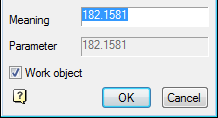
Enter a parameter expression to control the size. The parameter can be set by a variable name or expression that is allowed to use the number and names of the variables related to mathematical and logical functions.
| Important! | Object parameter names should not coincide with the names of the teams nanoCAD (for example, can not be assigned to the parameter name HATCH or LINE) |
Expressions can be used the following functions:
-
arithmetic operators +, -, *, /
-
trigonometric functions sin(), cos(), tg() (the function argument is given in degrees)
-
inverse trigonometric functions asin(), acos(), atg()
-
taking the square root function sqrt()
-
exponentiation function^ (recording format: x ^ y - x raising y)
-
absolute value abs()
-
rounded to an integer value int().
Logical operations:
-
Min(x,y) - returns the minimum value of the argument;
-
Max(x,y) - returns the greatest value.
-
Iff (boolean, x, y) - returns the value of the argument x if the logical expression is true, or the value of y if the logical expression is false. Example of using the function, the result of which is similar to the function Min (x, y): Iff(x<y, x, y).
Valid logical conditions: >, <, == (equal), ! = (Not equal), > = (not less than), <= (not more).
Function within an expression can be nested.
Setting the graphic element
When you set a graphic element sketch (segment, circle arc, circle, spline or shading) dialog box will look like:
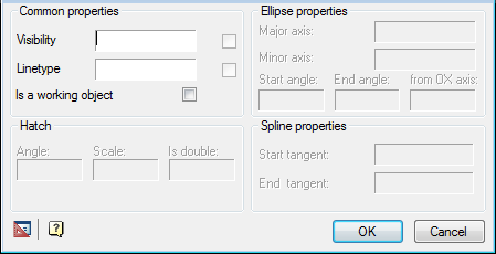
Work items are supporting the construction of a thumbnail and are not displayed when you insert a model from the database. Performance object can be any graphic sketch element: line, arc of a circle, etc.
Setting the insertion point
When setting the insertion point, a dialog box will look like:
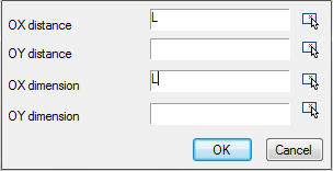
Distance along the axes OX and OY determines the position of the handle in the object. Distance can be set expression or numeric value.
Parameter on the x-axis and OX and OY is the name of the script variable whose value will change when stretching the handle.
Button  specify parameter lets take a parameter or drawing away.
Enter additional values
In the sketch may include additional expressions for calculation of parameters. These expressions should be written a single line text entry format each line of text as follows:
X = EXPR
where X - the variable name;
EXPR - an expression that contains the names of variables, mathematical or logical functions.
Examples of additional rows of values:
-
a = b*2 - assigning the result of an arithmetic operation;
-
alpha = asin(b/c) - the use of trigonometric functions;
-
k = iff(a>b, 1, 0) - assign a value to the condition;
-
d = min(m1, 100) - the assignment of the smallest of the two values;
-
g10 = sin(alpha*2) + sqrt(b^2 - c^3) / min(sin(a), cos(b)) - nested functions.