
 De
De  Es
Es  Fr
Fr  Pt
Pt 

nanoCAD Platform Help
-
-
-
-
-
-
-
-
-
-
-
-
-
-
-
-
-
-
-
-
-
-
-
-
-
-
-
-
-
-
-
-
-
-
-
-
-
-
-
-
-
-
-
-
-
-
-
-
-
-
-
-
-
-
-
-
-
-
Section
-
-
-
-
-
-
-
-
-
-
-
-
-
-
-
Section
 Main menu: Mechanical - Symbols - Views, Sections >
 Sections.
Ribbon: Mechanical - Symbols >Sections.
Toolbar: Sections (toolbar " Symbols").
 Command line: MCSECT.
Procedure
1. Call command;
2. Select the path type: Arc or Segment. Each type has its own order of construction;
- Type Segment. Allows you to create a section as a polyline;
- Specify the first point of the section;
- Specify the subsequent cut points. To finish entering points, press "Enter";
- Type Arc. Creates an arcuate cut;
- Select the desired arc construction method: Arc (3 points), Arc (2 points and bend), Arc (2 points and center);
- Draw an arc in accordance with the selection.
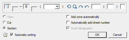
3. Select the direction of the cut arrows. A dialog box appears "Section";
4. In the dialog box, enter the required parameters. Press the button "OK";
5. Insert the section symbol in the drawing.
| Note: | When you transfer the designation by means of nanoCAD, the integrity of the data in terms of specifying the mutual location and specifying the zones of the drawing can be violated. In this case, you must run the "Update" command. |
Editing
Editing is done by double-clicking the LMB on any element of the symbol. This opens the "Views, cuts, sections" dialog box, where you can change the required parameters.