
 De
De  Es
Es  Fr
Fr  Pt
Pt 

-
-
-
-
-
-
-
-
-
-
-
-
-
-
-
-
-
-
-
-
-
-
-
-
-
-
-
-
-
-
-
-
-
-
-
-
-
-
-
-
-
-
-
-
-
-
-
-
-
-
-
-
-
-
-
-
-
-
Scale fragment view
-
-
-
-
-
-
-
-
-
-
-
-
-
-
-
-
Scale fragment view
 Main menu: Mechanical - Symbols - Views, Sections >
 Scale fragment view.
Ribbon: Mechanical - Symbols >Scale fragment view.
Toolbar: Scale fragment view (toolbar " Symbols").
 Command line: MCEVIEW.
Procedure
1. Call command;
2. Specify the center of the circle (rectangle);
3. Select the type of contour: Circle or Rectangle;
4. Specify the size of the circle (rectangle);
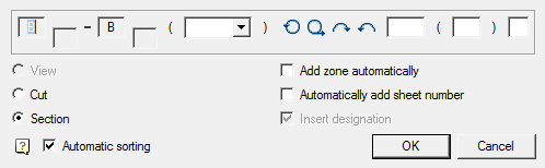
5. Specify the position of the symbol shelf. A dialog box appears "Views, cuts, sections";
6. In the dialog box, fill in the required fields. Press "OK";
7. Specify the insertion point of the symbol.
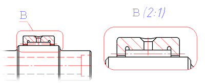
Placing an enlarged view of the selection
| Note: | When you transfer the designation by means of nanoCAD, the integrity of the data in terms of specifying the mutual location and specifying the zones of the drawing can be violated. In this case, you must run the "Update" command. |
Editing
Editing is done by double-clicking the LMB on any element of the symbol. This opens the "Views, cuts, sections" dialog box, where you can change the required parameters.