

 De
De  Es
Es  Fr
Fr  Pt
Pt 

-
-
-
-
-
-
-
-
-
-
-
-
-
-
-
-
-
-
-
-
-
-
-
-
-
Rotate
-
-
-
-
-
-
-
-
-
-
-
-
-
-
-
-
-
-
-
-
-
-
-
-
-
-
Rotate
 Ribbon: Home, Draw – Modify >
  Rotate
Menu: Modify – Rotate
Toolbar: Modify –
 Hotkeys: CTRL+E
Command line: RO, ROTATE
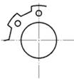
The command rotates the selected objects to a specified angle around the specified point.
Command options:
|
? |
Opens the additional options to select objects. |
|
Copy |
Rotates a copy of the selected object. |
|
Reference angle |
Specifies the angle from the reference angle. |
|
Points |
Specifies the angle from the reference angle to the line specified by two points. |
|
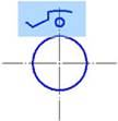
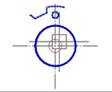
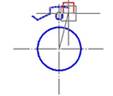
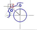
Selection of objects |
Specifying a reference line by two points |
Specifying rotation angle |
Result |
|
|
|
|
|
|
|
Command prompts:
|
Select objects or [?]: |
Select objects. Press ENTER when the selection is finished. |
|
Specify base point: |
Specify a base point. |
|
Specify rotation angle or [Copy/Reference angle]: |
Select the Copy option. |
|
Specify rotation angle or [Copy/Reference angle]: |
Select the Reference angle option. |
|
Specify the reference angle: |
Specify a first point of reference. |
|
Specify second point: |
Specify a second point of reference. |
|
Specify the new angle or [Points]: |
Specify the angle. |
The Rotate 3D (ROTATE3D) command is used to rotate the selected objects around a 3D axis. The rotation axis can be specified in several ways: by specifying two points or an object; parallel to the axes of the coordinate system; perpendicular to the plane of the current viewport.
|
|
Note |
|
When working with 3D objects, use the 3D Module editing commands. |

Command options:
|
? |
Opens additional object selection options. |
|
Object |
Aligns the rotation axis with an existing object. Object types: · line – the rotation axis is aligned with the selected line; · polyline – the rotation axis is aligned with the selected polyline segment. Straight line segments are treated as segments, arc segments – as arcs; · circle – the rotation axis is aligned with the 3D axis of the circle perpendicular to its plane and passing through the center; · arc – the rotation axis is aligned with the 3D axis of the arc perpendicular to its plane and passing through the center. |
|
Last |
The rotation axis is aligned with the last specified rotation axis. |
|
View |
The rotation axis is perpendicular to the plane of the current viewport through the selected point. |
|
X axis, Y axis, Z axis |
The rotation axis is aligned with one of the standard axes (X, Y, or Z) passing through the selected point. |
|
2points |
The rotation axis is specified by specifying two points. |
|
First point of the axis |
Specifies the first of two points of the rotation axis. |
|
Second point of the axis |
Specifies the second point of the rotation axis. |
|
Rotation angle |
Specifies the angle of the object rotation around the rotation axis. |
|
Reference angle |
Specifies the base angle for calculating the rotation angle. The object is rotated by an angle equal to the difference between the rotation angle and the reference angle. |
Command prompts:
|
Select objects or [?]: |
Select objects. Press ENTER when selection is completed. |
|
Specify first point or [Object/Last/View/X axis/Y axis/Z axis/2points] <2points>: |
Select the method for specifying the rotation axis: Object/Last/View/X axis/Y axis/Z axis /2points. The 2points method is set by default. |
|
|
· 2points method |
|
|
Specify first point on plane: – specify the first point of rotation axis. |
|
|
Specify second point on plane: – specify the second (end) point of rotation axis. |
|
|
· Object method |
|
|
Select a line, circle, arc or 2D-polyline segment: – select an object to create the rotation axis based on this object |
|
|
· Last method |
|
|
Uses the last specified rotation axis. |
|
|
· View method |
|
|
Specify a point on a section plane: – specify a point through which the rotation axis passes (perpendicular to the plane of the current viewport). |
|
|
· X axis method |
|
|
Specify a point on the YZ-plane <0,0,0>: – specify a point through which the rotation axis passes (perpendicular to the YZ-plane). |
|
|
· Y axis method |
|
|
Specify a point on the ZX-plane <0,0,0>: – specify a point through which the rotation axis passes (perpendicular to the ZX-plane). |
|
|
· Z axis method |
|
|
Specify a point on the XY-plane <0,0,0>: – specify a point through which the rotation axis passes (perpendicular to the XY-plane). |
|
Specify rotation agngle or [Reference angle]: |
Enter the rotation angle value, press ENTER. Or specify the first point of the angle on the screen. |
|
Specify end point: |
Specify the second point of the angle. |
|
|
If necessary, select the Reference angle option. |
|
|
Specify reference angle: – enter the value of the reference angle or the first point of the reference angle. |
|
|
Specify end point: – specify the second point of the reference angle. |