
 De
De  Es
Es  Fr
Fr  Pt
Pt 

-
-
-
-
-
-
-
-
-
-
-
-
-
-
-
-
-
-
-
-
-
-
-
-
-
-
-
-
-
-
-
-
-
-
-
-
-
-
-
-
-
-
-
-
-
-
-
-
-
-
-
-
-
-
-
-
-
-
-
-
-
-
-
-
-
-
-
-
-
-
-
Rivet joint
-
-
-
-
-
-
-
-
-
Rivet joint
 Main menu: Construction - Library objects >
 Rivet joint.
Ribbon: Construction - Library objects >Rivet joint.
Toolbar: Rivet joint ( "Library objects").
 Command line: SPRIVET.
Insertion tool riveted joint parts of the base standard elements nanoCAD Construction .
- Specify the starting point for drawing the rivet assembly.
- Specify the endpoint of the rivet assembly. When you insert the available tools of choice destinations rendering .
- In the dialog box mounting parts adjust the view of the rivet connections.
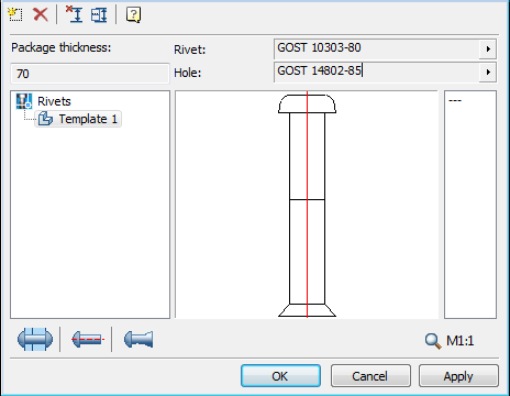
To select the type of rivet base nanoCAD Construction click in the rivet.
To select the type of base openings nanoCAD Construction click in the hole for rivets.
It is possible to save the template riveted joint for later reuse assemblies with the same set of items. To work with templates use the buttons at the top of the dialog box, and below is a list of available templates:
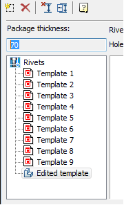
"Editable Template" stores the current settings bolting. It can not be deleted.
Button  Create a new template. Adds a new blank template.
Button  Delete template. Deletes the selected template from the list.
In the context menu templates available commands:
- Add Folder
- Delete object
- Rename
- Import from file
- Export to file
- Send by email
- Copy
These commands are similar to those used in in the Object Manager nanoCAD Construction .
Button  Select the insertion point and the length of the riveted joint. Designed to re-select the insertion point and the length of the rivet assembly drawing.
Button  Set package connection manually. Opens setup package of the parts.
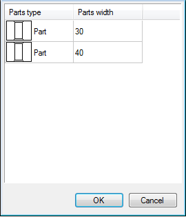
Left-click on one of the cells in the column "type items" to switch the item / gap:
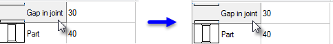
In the "Thickness" is set to the thickness of the relevant part (or gap) After configuring the package connected, close the window by pressing OK.
The right side of the dialog box mounting parts is a list of values diameter rivets.
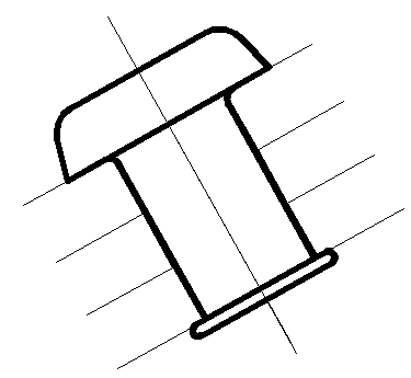
When you insert the rivet connections are available 3 ways to display selected button Insert mode riveted joint at the bottom of the dialog box toolbar. Drawing on the button displays the currently selected display method:
 With a local cutaway
 Normal Box
 Insert hidden
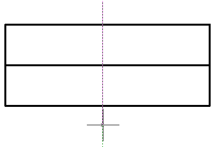
2 types available (front and side) display riveted joint:
 Front view
 Left side view
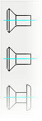
You can choose the type rivet connections:
 |
The number of types depending on the type of rivet. |
Automatic detection of packet connection
When you insert the rivet connections made automatically recognize the boundaries of the parts. If the line crosses the insertion direction perpendicular to a few segments in the drawing, they are defined as the boundaries of parts and installs Connection:
Insertion point and the length of the rivet assembly are determined automatically based on the thickness of the package details.
Editing riveted joint
A dialog box settings riveted joint, apply any of the standard editing tools to the centerline of the group details.
If the settings nanoCAD Construction included tooltips, then when you move the cursor to the center line will show "Rivet connection".