De
De  Es
Es  Fr
Fr  Pt
Pt 

-
-
-
-
-
-
-
-
-
-
-
-
-
-
-
-
-
-
-
-
-
-
-
-
-
-
-
-
-
-
-
-
-
-
Reports Creation
-
-
-
-
-
-
-
-
-
-
-
-
-
-
-
-
-
-
-
-
-
-
-
Reports Creation
Reports are used to arrange information about objects in the drawing.
Recommended report structure:
· First page header;
· Header;
· Last page header;
· Report title;
· Report template;
· Report;
· Report result;
· First page footer;
· Footer;
· Last page footer.
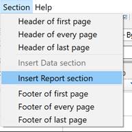
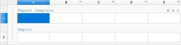
To create a report in the table editor, open the menu bar command Section – Insert Report section. The command will create the Report template subsection.
Using the Report Template menu, additional subsections are added: Report Header, Report, Report Result.
Header and footer sections are added in the Sections menu.
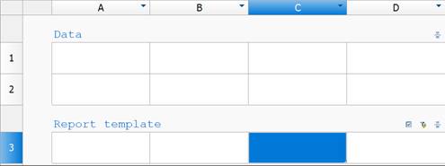
The report template defines how the content is displayed in the report and can contain one or several lines. A copy of the template rows is created for every object. Formulas are calculated according to the properties of the selected objects.
The following command are available in the Report template menu (click the subsection commands):
· Object filter... – opens the Quick selection dialog for forming a selection of drawing objects. The command is duplicated by the  Select source objects button on the right in the Report Template section.
· Merging and grouping... – opens the Grouping and merging dialog in which the parameters for grouping and merging table cells are configured. The command is duplicated by the  Group and merge button on the right in the Report Template section.
· Freeze report – a switch that controls the report update mode. If the switch is enbaled, the update is performed manually, the Update report command becomes available.
· Update report – updates the values of report objects, the command is available in the manual update mode.
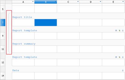
· Report header – adds the Report title subsection to the beginning of the report, displayed at the beginning of each table.
· Append Data section – adds the data section below the report. If the section already exists, an additional row is appended.
· Append Report section – adds a new report below the current one.
· Remove report – deletes the report with all associated subsections.
· Rebuild – completely rebuilds the report according to the report template. Data entered manually in the Report section will be overwritten.
· Convert to Data section – the command converts report sections to data. Empty lines are not converted. When the command is started , the Conversion Options dialog box opens.
· Report footer – adds the Report summary subsection to the end of the report, displayed after each table section.
All related subsections of the report are visually united by a bracket.
IMPORTANT! The report template has absolute priority over user changes. The report decorated by the user after the update will become the same as the report template specified. Automatic report lines corresponding to the collected objects will be automatically formatted strictly according to the report template.
The Report displays the values of the template variables.
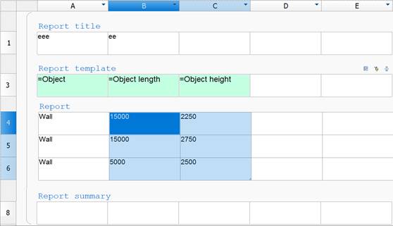
The report contains cells containing object data marked with a special color. Selecting the cells highlights the corresponding objects in the drawing.
If you edit such cells, changes are applied to the object to which they belong. For example:
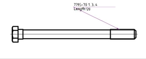
1. Take a bolt 7795-70 with a length 50 mm and put a leader on it.
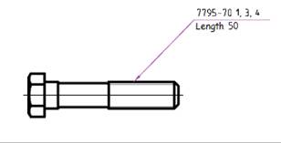
2. Create the table, the report template and link to a bolt (parametric object).
3. Add the parameters: Object.Name and Object.L.
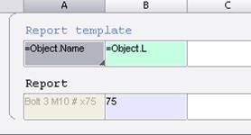
Enter a new length, for example 120. Close the table editor.
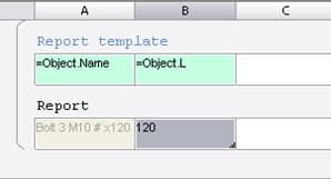
The bolt’s length is changed.