De
De  Es
Es  Fr
Fr  Pt
Pt 

-
-
-
-
-
-
-
-
-
-
-
-
-
-
-
-
-
-
-
-
-
-
-
-
-
-
-
-
-
-
-
-
-
-
-
-
-
-
-
-
-
-
-
-
-
-
-
-
-
-
-
-
-
-
Port
-
-
-
-
-
-
-
-
-
-
-
-
-
-
-
-
-
-
-
-
-
-
-
-
-
Port
 Main menu: Construction - Communications >
 Port.
Port.
Toolbar: Communications >Port.
 Command line: SPPORT.
This command is used to insert the object "Port" of Template manager.
Insertion
1. Call the command insert the connector. You will be prompted to insert the connector of the last used template library, or, if not, the port by default.

2. Select the appropriate connector if necessary. To do this in the context menu, select "Dialog". On the form template library select the port and confirm the selection.
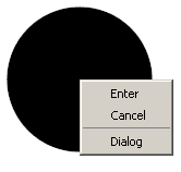
3. Select the base point and the direction of insertion.
4. Continue to insert the ports (point 1,2,3) or end (press Enter).
| Note: |
Equipment, trace and ports when inserting receive a unique number (the "Number" in the properties) |
Editing
Edit location
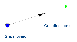
The object "Port" has two grips:
- Grip moving- it allows you to move an object,
- Grip directions- changes the direction of the object.
Editing options
Call for editing by choosing from the context menu of a selected object the command "Edit" or double-clicking on the object editing.
When you call opens the edit form, this form Template library.
The process of editing the object "Port" is similar to the process of editing the template "Port".
Save as Template
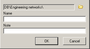
If you want to save the object "Port" as a template to be:
- In the form of editing select "Save as Template"
 .
. - In the form of "Create element" and enter the name of the note.
- Confirm entry. The equipment will be added to the Template library.