
 De
De  Es
Es  Fr
Fr  Pt
Pt 

-
-
-
-
-
-
-
-
-
-
-
-
-
-
-
-
-
-
-
-
-
-
-
-
-
-
-
-
-
-
-
-
-
-
-
-
-
-
-
-
-
-
-
-
-
-
-
Plotter Settings
-
Plotter Settings
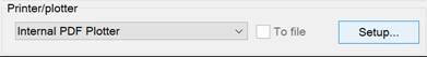
The Printer/Plotter section of the Page Setup and Plot dialogs contains a list of all plotting devices registered in the system. Their parameters can be edited by clicking the Setup button to the right of the list.
The type of dialog box that opens and the settings parameters are determined by the driver of the current plotting device.
nanoCAD has the ability to convert and output drawings using internal printers into files of the following formats:
· DWFx (Internal DWFx Plotter),
· DWF (Internal DWF Plotter),
· EMF (Internal EMF Plotter),
· PDF (Internal PDF Plotter),
· TIF, TIFF, BMP, JPG, JPEG, PNG, PCX, ECW (Internal Raster Plotter).
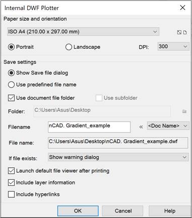
For internal plotters, the settings dialog has the following general parameters:
Paper size and orientation
|
|
Drop-down list to select paper formats. |
|
|
The button opens the Modify paper format dialog to edit the set paper format. |
|
|
The button opens the Add paper format dialog to add a new paper format. |
|
Portrait |
Sets the portrait orientation of paper. |
|
Landscape |
Sets the landscape orientation of paper. |
|
DPI: |
Sets the plot resolution. |


Save settings
|
Show Save file dialog |
Enables the mode to open the standard dialog for specifying the name and location of the file. |
|
Use predefined file name |
Enables the mode of saving the file with the document name (the file name and its save path are displayed in the File name: field). |
|
Use document file folder |
Enables/disables the mode of saving the file in the original document folder. |
|
Use subfolder |
Enables/disables the mode of creating an additional directory with the format name (DWFx, DWF, EMF, PDF or Raster). The parameter is available when the Use predefined file name and Use document file folder modes are enabled. |
|
Folder: |
Displays the path to the file storage folder. By default, the folder containing the original document is set. You can select a different folder for saving the file by unchecking the Use document file folder box and clicking the |
|
Filename: |
Specifies a template for the file name. The file name entered in this field can be automatically supplemented with the name of the source document, layout name, user name, etc., separated from the file name and from each other by the underscore character (_). |
|
|
Drop-down list of variables for forming a file name template. Available variables: · <DN> – <Doc Name> – adds the name of the source document to the name of the file being created. · <LN> – <Layout Name> – adds the name of the layout of the source document to the name of the file. · <UN> – <User Name> – adds the user name to the name of the file being created. · <T> – <Time> – adds the file creation time to the name of the file being created. · <D> – <Date> – adds the file creation date to the name of the file being created. · <C1> – <Counter1> – adds a serial number (index) to the name of the file being created in the format 1, 2, 3, etc. · <C2> – <Counter01> – adds a serial number (index) to the name of the file being created in the format 01, 02, 03, etc. · <C3> – <Counter001> – adds a serial number (index) to the name of the file being created in the format 001, 002, 003, etc. · <C4> – <Counter0001> – adds a serial number (index) to the name of the file being created in the format 0001, 0002, 0003, etc. · <C5> – <Counter00001> – adds a serial number (index) to the name of the file being created in the format 00001, 00002, 00003, etc. · <C6> – <Counter000001> – adds a serial number (index) to the name of the file being created in the format 000001, 000002, 000003, etc. · <_> – <Separator> – adds an underscore (_) to the name of the file being created. All variables are automatically separated by an underscore (_) when added to an existing file name template. If necessary, the underscore (separator) can be inserted into the template manually by selecting it from the drop-down list. |
|
File name: |
Displays the path and the specified file name. |
|
If file exists: |
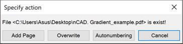
Drop-down list to specify the action when saving a file with the name of an existing file: · Show warning dialog. When you specify this option, the Specify action dialog opens after clicking the Plot button:
Action options: · Add Page – append the output layouts of the document to the pages of the existing file; · Overwrite – re-save the existing file; · Autonumbering – save in a new file with the name of the existing file, to which a serial number is automatically added. · Always overwrite existing file – overwrite the contents of the existing file. · Auto numbering file name – save the file with a new name consisting of the name of the existing file and a serial number (index) automatically added to it. · Append page to existing file – add output sheets of the document to the pages of the existing file. The parameter is available for files of DWFx, DWF, PDF, TIF format. |
 button.
Internal DWFx Plotter, Internal DWF Plotter
Additional save settings:
|
Launch default file viewer after printing |
Enables/disables opening of a printed file in the DWFx, DWF file viewer installed on the computer. |
|
Include layer information |
Enables/disables adding layer information to a DWFx, DWF file. |
|
Include hyperlinks |
Enables/disables converting document hyperlinks to hyperlinks in a DWFx, DWF file. |
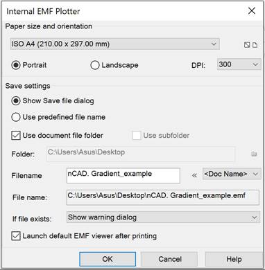
Additional save settings:
|
Launch default EMF view after printing |
Enables/disables opening of a printed file in the EMF file viewer installed on your computer. |
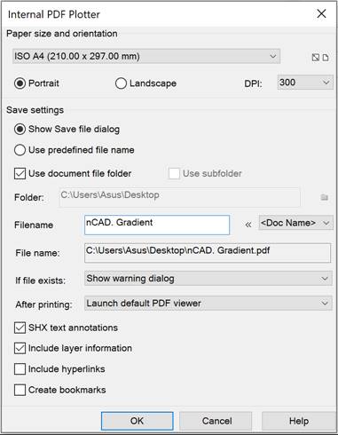
Additional save settings:
|
After printing: |
Drop-down list for specifying the action after printing: · Do nothing. · Launch default PDF Viewer – opens the printed file in the PDF viewer installed on your computer. · Show print dialog – launches the print dialog in the PDF viewer installed on your computer. |
|
SHX text annotations |
Enables conversion of SHX texts into PDF comments. To search for text in PDF document viewers, activate the "Enable comments" function in the search settings . You can also control the enabling/disabling of comments using the PDFSHX system variable : PDFSHX = 0 – comments are not created (text elements using SHX fonts are visually saved as geometric objects) ); PDFSHX = 1 – comments are created based on text objects using SHX fonts. |
|
Include layer information |
Enables/disables adding layer information to a PDF file. Uncheking this box can optimize further work with PDF files. |
|
Include hyperlinks |
Enables/disables converting document hyperlinks to hyperlinks in a PDF file. |
|
Create bookmarks |
Enables/disables adding bookmarks to layouts and named views in a PDF file. |
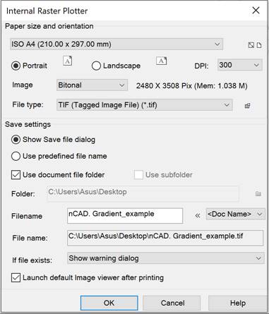
Additional save settings:
|
File type: |
Drop-down list for selecting the format of the image being created: TIF, TIFF, BMP, JPG, JPEG, PNG, PCX or ECW. For TIF, TIFF, JPG, JPEG, ECW formats, the save settings are available, which are opened by the |
|
Image: |
Drop-down list for selecting the raster type: Bitonial, 8-bit indexed, Grayscale, RGB Colors. Depending on the selected file type and raster type, the size of the raster image being created is displayed to the right of the list. |
|
Launch default Image viewer after printing |
Enables/disables opening of the printed file in the raster file viewer installed on the computer. |
 button. Depending on the selected file type, clicking the button opens the corresponding dialog box TIFF Options, JPEG Options, ECW Options.
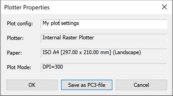
Saving Plotter Settings to PC3 File
When you finish changing the settings, when you close the dialog, you will be prompted to save the settings as a separate file with the PC3 extension so that you can reuse it.
For internal printers, the following settings are not saved:
· SHX text annotations, since enabling/disabling comments can also be controlled using PDFSHX system variable,
· After printing action is always set to open in a file viewer.
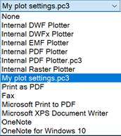
After this, the saved configuration can be selected in the list of plotters.
File with PC3 extension is saved in the print configuration files C:\Users\User_name\AppData\Roaming\Nanosoft AS\nanoCAD x64 26.0\PlotConfigs. You can change the location in the Standard Directories of the Options dialog.
Such printer device configurations can be transferred to different computers and shared among workgroup members, provided that the same driver version and plotter device model are used. If the plotter driver version is updated, the previous PC3 file may not work. Plot configurations for system plotters can also be shared, but should be in the same version of the operating system.