
 De
De  Es
Es  Fr
Fr  Pt
Pt 

-
-
-
-
-
-
-
-
-
-
-
-
-
-
-
-
-
-
-
-
-
-
-
-
-
-
-
-
-
-
-
-
-
-
-
-
-
-
-
-
-
-
-
-
-
-
-
-
-
-
-
-
-
-
Plate Array
-
-
-
-
-
-
-
-
-
-
-
Plate Array
 Main menu: Mechanical - Utilities >
 Plate array.
Ribbon: Mechanical - Utilities >Plate array.
Toolbar: Plate array (on toolbar "Utilities").
 Command line: MCPLTARRAY.
Command to tile layouts for a given circuit.
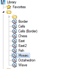
- Choose from a base tile pattern and place it on the drawing.
- Press the plate array.
- In the opened window, click the plate shema and specify the token group.
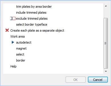
- Select Trim mode extreme tiles .
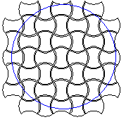
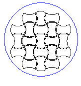
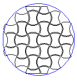
- Trim plates by area border - tiles clipped to the boundary of the layout. Circuit tile becomes open. This tile is taken into account in property "Cut". This mode is not available if you enable the check box "Make each tile a separate."
- Include trimmed plates - extreme tiles stacked atop circuit layout.
- Exclude trimmed plates - tiles, overlapping circuit layouts do not fit.
- Sect border type face- if tiles have execution end elements will be selected most podhodyaeschee. When the layout of the area selected by the execution system names: Whole, Left, Right, Top, Bottom. When the layout along the border all versions checked sequentially, regardless of names.
Trim plates by area border Include trimmed plates Exclude trimmed plates Sect border type face 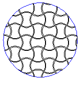
- Create each plate as a separate object.
If the box is checked, the result will be a group of independent layout objects - copies of the original objects. This mode does not support cutting elements on the boundaries of the area, but allows more flexibility to edit the result.
When the check box is created off a single object that includes all geometry. In the properties of this object will be information on the number, weight and costs of each type of tiles, as well as the total weight (based on the whole tiles) and cost. You can delete individual tiles by clicking on them with the right. In this case the total amount will be adjusted, weight and cost.
- Determine the work area tiles.
- auto detect - layout area defined contour, which is located inside the tile pattern. In the inner islands stacked tiles will not.
- magnet - loop selection tool "magnet".
- select - area layout is selected in the drawing indicating one or more loops.
- border - tiles splits along the perimeter or primitives nanoCAD. Cropping mode in this case will simulate laying curbs.
- To complete the command, press OK.
| Note: | Creating a template tile layouts can be done using Object Wizard. |