

 De
De  Es
Es  Fr
Fr  Pt
Pt 

-
-
-
-
-
-
-
-
-
-
-
-
-
-
-
-
-
-
-
-
-
-
-
-
-
-
-
-
-
-
-
-
-
-
-
-
-
-
-
-
-
-
-
-
-
-
-
-
-
-
-
-
-
-
-
-
-
-
-
-
-
-
-
-
-
-
-
-
-
-
-
-
Override main lines
-
-
-
-
-
Override main lines
 Context menu: Override main lines (on the selected object).
 Command line: SPOVERRIDEMAINLT, OVERRIDEMAINLT.
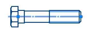
Users sometimes need to make retrofit drawings that show both new and existing objects at the same time.
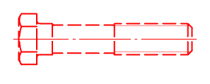
That is, for example, welding new fittings into an existing tank. In this case, the main lines of existing objects (fittings, hatches, bolts, shells, bottoms and any other elements of the base) should be depicted either as thin or dashed lines.
To change these parameters, use the "Override main lines" command.
Procedure
1. Select the standard elements to override.
2. Call the "Override main lines" command. The "Overriding the main lines" dialog opens.
3. Specify the required parameters.
4. Click the "OK" button. The main lines of the selected objects will be overridden.
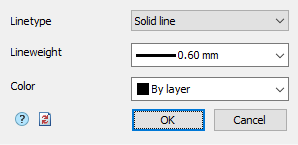
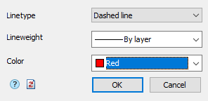
Dialog
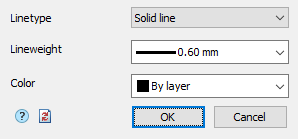
Linetype - the parameter allows you to select the line type from the list: Solid or Dashed line.
Width - the parameter allows you to select the line thickness from the list.
Color - the parameter allows you to select the color of the lines.
Button  "Clear all redefinitions" - removes all previously made overrides, brings the selected objects to the default settings.