-
-
-
-
-
-
-
-
-
-
-
-
-
-
-
-
-
-
-
-
-
-
-
-
-
-
-
-
-
-
-
-
-
-
-
Options Tab
-
-
-
-
-
-
-
-
-
-
-
-
-
-
-
-
-
-
-
-
-
-
-
-
-
Options Tab
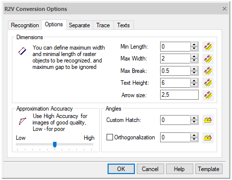
To optimally configure the raster entities recognition algorithms on a certain raster image, you can use information on measurement values of raster objects in the Options tab.

Options tab
Options values can be entered from the keyboard or measured on the screen.
Measuring option value on the screen
Click the button located next to the corresponding dialog field ( or
or  ).
).
Specify two points in the image.
In the process of measurement, the program draws a “rubber” line connecting the specified points, therefore, in the text below the process of measurement in the image will be defined by the draw a line term. At the end of the measurement, the value is entered into the corresponding field.
Raster vectorization options
|
Option |
Description |
|
Min. Length |
Specifies the minimum length of a raster fragment that should be recognized as a line, circle or arc during vectorization. Set the value of this parameter equal to the length of the shortest raster line or the diameter of the smallest raster circle (arc). When measuring in the image, draw a line along the smallest raster line, arc or circle. Min. Length value will be equal to the length of the drawn line. |
|
Max. Thickness |
Specifies the maximum thickness of a raster object that should be recognized as a line, arc or polyline. Set this value to slightly larger than the maximum thickness of the raster line to be vectorized using the Lines, Arcs and Circles or Polylines algorithms. If the program does not vectorize raster lines, circles, arcs of the image, increase the value of this option. If the program does not approximate filled raster areas with boundary objects, reduce the value of this option. When measuring distances in the image, the measurement (“rubber”) line should be drawn perpendicular to the thickest raster line, which should be recognized using Lines or Arcs algorithm or approximate using the Polylines algorithm. The measured value will be equal to the length of the part of the drawn line that passes along the raster line. |
|
Max. Break |
Specifies the maximum length acceptable for ignored raster lines break. If a line (arc) in the image is split into two parts, and you need to vectorize this line (arc) as a single vector object, set the option value, which exceeds the distance between these two parts. The break will be eliminated, and the parts of the vector line (arc) will be connected. When measuring in an image, draw a line along the largest break in the raster line (arc). This value will be equal to the length of the part of the drawn line that passes along the break. |
|
Arrow size |
Specifies the width and length of the object to be recognized as an arrow at the ends of the line. To determine the arrow dimensions, enter values in the field, separated by commas, or click the button and draw a rectangle that delimits the arrow. |
|
Text height |
Set this value equal to the maximum height of upper case raster text characters. When measuring in the image, draw a line over the raster text. The Text Height value will be equal to the distance between the first and last image points that fall on the drawn line. |


 De
De  Es
Es  Fr
Fr  Pt
Pt 
