De
De  Es
Es  Fr
Fr  Pt
Pt 

-
-
-
-
-
-
-
-
-
-
-
-
-
-
-
-
-
-
-
-
-
-
-
-
-
-
-
-
-
-
-
-
-
-
-
-
-
-
-
-
-
-
-
-
-
-
-
-
-
-
-
-
-
-
-
-
-
-
-
-
-
-
-
-
-
-
-
Offset dimension
-
-
-
-
-
-
-
-
-
-
Offset dimension
 Main menu: Dimensions >
 Offset dimension.
Ribbon: - Symbols >Offset dimension.
Toolbar: Dimensions>Offset dimension.
 Command line: SPDIMOFFSET, DIMOFFSET.
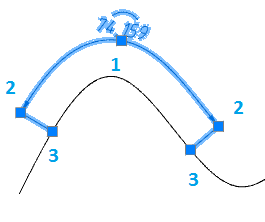
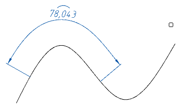
The command allows you to build a size similar to the contour of the selected object. Similarity size is indicated by an arc above the value.
Procedure
1. Call the command "Offset dimension".
2. Select the method for specifying the object: "sElection" or "frEe". The "sElection" method is used in paper space when you need to dimension an object in an inactive viewport. In all other cases, the "frEe" method is used.
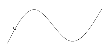
3. Specify the object from which the dimension will be built. The selected object can be specified: line, arc, spline, polyline, circle or ellipse.
4. Specify the first insertion point (starting point of origin of the dimension) or press the "Space" (or RMB) to automatically add endpoints to the entire length of the object (does not work for closed objects).
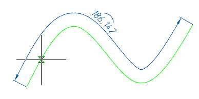
5. Specify the second insertion point (end point of origin of the dimension), if you have not pressed the "Space" (or RMB) key.
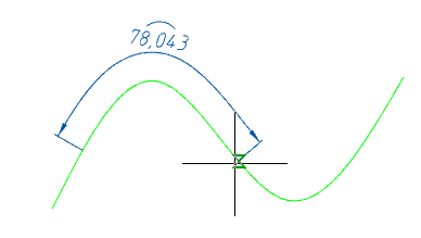
6. Place the dimension leader in the drawing.
7. Offset dimension will be built. The command will continue to work in a cyclic mode. Press the "Esc" key to exit cyclic mode.
Grips
1. Dimension value placement grip.
2. Extension line position grips.
3. Dimension endpoint grips.