-
-
-
-
-
-
-
-
-
-
-
-
-
-
Object Snap Tracking Mode
-
-
-
-
-
-
-
-
-
-
-
-
-
-
-
-
-
-
-
-
-
-
-
-
-
-
-
-
-
-
-
-
-
-
-
-
Object Snap Tracking Mode
 Menu: Tools – Drafting settings… Object snap tab
 Status bar: the
  button
 Hotkeys: F11
 Command line: DDRMODES, DSETTINGS, SE
The object snap tracking mode allows the placing of created objects in specific relation to other created objects. When object snap tracking mode is switched on, nanoCAD temporarily displays dotted trajectories of different types (tracking lines) for accurate positioning of objects.
Object tracking modes are used together with object snap and works when the cursor’s pickbox is near a probable point of object snap (the pickbox size determines the zone of tracking lines activation). Object tracking expands and adds to the capabilities of object snap.
The parameters of object tracking are specified in the Tracking and Object Snap tabs in the Drafting Setting dialog box and in the context menu of the OTRACK button.

Parameters:
|
Object Snap Tracking On (F11) |
Switches object snap tracking mode on/off. |
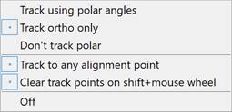
The context menu of the OTRACK button:
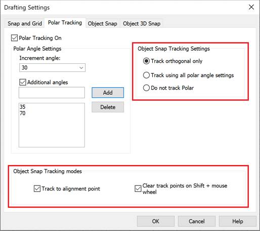
Object Snap Tracking modes
|
Track to alignment point |
Switches on/off the display of tracking lines to an object’s characteristic points. |
|
Clear track points on “shift + mouse wheel” |
Switches on/off the erasing mode of the snap point marker on a tracking line using SHIFT and the mouse wheel. When the mode is enabled, markers can only be erased using the “shift + mouse wheel” combination. When the mode is disabled, the markers are also erased when zooming/panning. |
Object snap
|
Track using polar angles |
Switches using object tracking together with polar tracking mode on/off. In this case, the tracking lines for all angles specified in the Polar Tracking tab in the Drafting Settings dialog box are displayed. |
|
Track ortho only |
Switches the display of tracking lines only in ortho directions on/off. |
|
Don’t track polar |
Switches off polar tracking mode. |
By default, object snap markers and tracking rays are displayed in green, and object tracking markers are displayed in blue. You can change the color in the Snap Settings section of the OPTIONS dialog.
To use object tracking mode:
1. Switch on the OTRACK and OSNAP modes in the status bar.
2. Use the cursor to capture the required characteristic objects’ points to set tracking lines. Place the cursor near a point to capture it. A captured point is marked with + symbol. To deactivate a point already captured, move the cursor over it again. You can clear all markers using zoom/pan operations or using the SHIFT key and mouse wheel if the Clear track points on Shift+mouse wheel box is checked.
3. Dotted tracking lines, going through one or several captured points and the cursor’s pick box, will appear when you move the cursor within the drawing. You can snap to points on those lines or to the intersection points. The more types of object snap that are switched on, the more points will be available for capture.
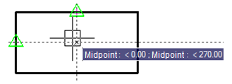
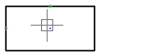
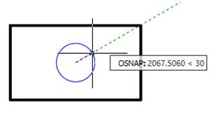
Example: Circle in the center of a rectangle.
1. Defining the center of rectangle:
Specifying the circle center:
2. Specifying the circle radius:


 De
De  Es
Es  Fr
Fr  Pt
Pt 
