
 De
De  Es
Es  Fr
Fr  Pt
Pt 

-
-
-
-
-
-
-
-
-
-
-
-
-
-
-
-
-
-
-
-
-
-
-
-
-
-
-
-
-
-
-
-
-
-
-
-
-
-
-
-
-
-
-
-
-
-
-
-
-
-
-
-
-
-
-
-
-
Object's graphic
-
-
-
-
-
-
Object's graphic
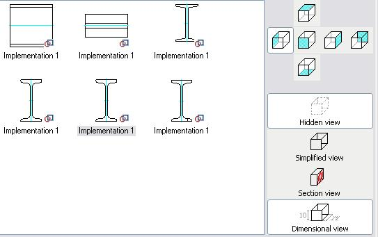
To display the object in the drawing, the orthogonal views are used. The views have different types: general, views with cuts and simple views with dimensions. The views with dimensions are system and hidden. Their graphic is realized when the dimensional view is inserted from the context menu.
The local coordinate system in 2D views is set that the X-axis is directed to the right and the Y-axis is directed up in the frontal view. The direction of the coordinate axes is defined by the projective dependence in the other views.
The parametric recognition defines the parameters and the relative position (horizontality, verticality, perpendicularity and parallelism) of the graphic primitives and their interaction with each other (intersection points, tangents etc.). It is necessary to specify the insertion point of the detail (origin of the local coordinate system). It is necessary to describe a view as a text (graphic parameterization).
Recommendations for creating 2D views.
- Use the object snap for endpoints and intersections.
- Use the polar tracking and ortho modes.
- Arc segments and tangent arcs should be dimensioned.
- Use the helping geometry for recognition (circles in the centres of the tangent arcs).
- Dimension should be clearly set.
- Sometimes to create a difficult graphic, the view is separated into parts, and null distance is set between the parts.
The purpose of the recognition is to define the position of all primitives towards the insertion point. The parameters and dimensions are set from it.
The requirements to graphic are specified in the particular recommendations.
To make a 2D graphic parametrically controlled, set the detail's geometric parameters as dimensions instead of the nominal sizes. Some parameters are related to graphics.
Common properties: "Visibility" - is a logic expression or variable, defining whether or not to draw the primitive.
Linetype:
- 0 - main.
- 2 - thin.
- 4 - dashed.
Work object - an object that is used in the recognition, but is not added to the end graphic. It is a helping drawing.
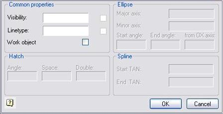
Parameters of hatch - the angle of slope, hatch space and double hatch feature (logical condition)
Parameters of ellipse - the major axis of the ellipse and the minor axis of the ellipse. The start angle and end angle of the ellipse - if the elliptic arc is drawn. The sloping angle to the OX axis is an angle, on which the local coordinate system of the ellipse is relatively rotated to the coordinate system of the objects view.
Parameters of spline - the start and end tangent angle. All points of the spline should be dimensioned.
If the hatch contour does not follow the required contour, a closed polyline is created with the parameter - hatch contour.
Sometimes it is necessary to set a contour of suppression for the detail (if the automatically created contour does not follow the requirements of the detail). In this case, the parameter of the suppression contour is also set for the closed polyline.
Creating the dimensional views of the standard details
The same graphic is used to create the dimensional views of the standard details, as is used to recognize the main view.
Add only the required elements to the graphic of the dimensional view.
To recognize the dimensions as constructive objects, switch off the Work object checkbox in the Parameter dialog.

After that, specify the required view of the object and select Hidden view and Dimensional view for it.
Select the Recognize view from the context menu.
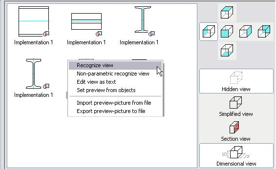
Specify the graphic in the drawing and confirm the selection. Save the object.
To test the dimensional view, insert the object with the created direction of view. From the context menu of this view, select the Add dimensional view.
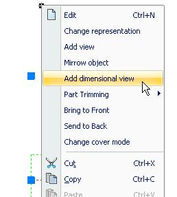
Specify the insertion point of the dimensional view.
| Note: |
Dimensional views are inserted with the current dimension style and symbol scale. |