
 De
De  Es
Es  Fr
Fr  Pt
Pt 

-
-
-
-
-
-
-
-
-
-
-
-
-
-
-
-
-
-
-
-
-
-
-
-
-
-
-
-
-
-
-
-
-
-
-
-
-
-
-
-
-
-
-
-
-
-
-
-
-
-
-
-
-
-
-
-
-
-
Mechanical note
-
-
-
-
-
-
-
-
-
-
-
-
-
-
-
-
-
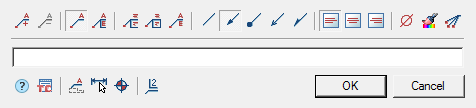
Mechanical note
 Main menu: Draw - Notes -
 Mechanical note.
Main menu: Mechanical - Symbols - Notes >Mechanical note.
Ribbon: Annotate - Leaders >Mechanical note.
Ribbon: Mechanical - Symbols >Mechanical note.
Toolbar: Notes >Mechanical note.
 Command line: MCNOTE, NOTE.
Procedure
- Call the command.
- If the option "Show dialog before inserting objects" is active, the "Mechanical note" dialog opens. In the "Mechanical note" dialog box, enter text and define the note options. Click "OK".
- Pick a point on the object (position of the leader arrow).
- Place a note leader in the drawing.
- If the "Show dialog before inserting objects" option is disabled, the "Mechanical note" dialog will open.In the "Mechanical note" dialog box, enter text and define the note options. Click "OK".
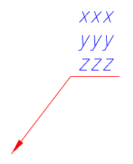
- Note will be biuld.
Menu
-
 Add string - command adds an extra input field;
 -
 Remove string - command deletes the input field where the cursor is located;
 -
 Simple note - command toggles the display of the note;
 -
 Multiline note - command toggles the display of the note;
 -
 Multi-line text - the switch controls the display of multi-line text on the shelf;
 -
 Frame - text under the shelf is framed;
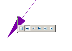
 - Type arrows:
-
 None,
None, -
 Arrow,
 -
 Point,
 -
 Open arrow,
 -
 Half-arrow,
 - Align text horizontally;
-
 By left edge
-
 By center
-
 By right edge
-
 Insert special symbol - the command allows you to insert a special character into the input field;
 -
 Match properties - command copies appearance parameters from another object;
 -
 Add extension line - the command allows you to add an additional note line;
 -
 Technical conditions;
 - Designations:
-
 Surface,
 -
 Dimension,
 -
 Others;
 -
 Dulling dimension.
Context menu
The context menu opens in the input field. View Context menu entry fields.
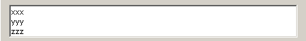
Fields
By default, "Mechanical note" contains one text box for the label above the leader flange.
Using the "Simple note" and "Multiline note" menu commands, you edit the presence of additional shelves.
Use the "Add string" and "Remove string" menu commands to edit the number of leader ledges. When using a simple note, these commands control the presence of text under the shelf.
| Note: |
Hotkeys are available for the |
The "Multi-line text" option allows you to display multiline text on the shelf. When this parameter is enabled, the transition to another line is performed by the "Ctrl + Enter" key combination.
Arrow type selection context menu
When you call the context menu on the note arrow (without selecting the note), a dialog box for selecting the arrow type will appear.
Auto sort modes
| Note: |
The submenu (in our example - the letter A) is activated in cases of using the auto sort mode when applying letters to the drawing. |
Surface - reference surface designation (When automatic lettering sorting is enabled).
Dimension -dimension designation.
Others - designation of other elements, such as holes.
Dulling dimension
- special note to indicate blunt edges.