
 De
De  Es
Es  Fr
Fr  Pt
Pt 

-
-
-
-
-
-
-
-
-
-
-
-
-
-
-
-
-
-
-
-
-
-
-
-
-
-
-
-
-
-
-
-
-
Notes
-
-
-
-
-
-
-
-
-
-
-
-
-
-
-
-
-
-
-
-
-
-
-
-
-
-
-
Notes
 Ribbon: Home, Annotate – Leaders –
  Mechanical notes
Menu: Draw – Notes >  Mechanical notes…
Toolbar: Utilities, Notes –
 Command line: NOTE
This command opens the Mechanical note dialog box to set the mechanical note options:
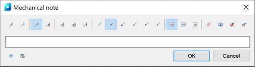
Options:
Use the icons to add/remove text input fields and to add a border:
|
|
Adds an additional input field. |
|
|
Removes the input field where the cursor is located. |
|
|
Switches a leader display - simple note. |
|
|
Switch a leader display - multiline note. |
|
|
Frames the text under the landing. |
|
|
Controls the output of the last line in a multiline note without a landing. |


Use the icons to select the style of the extension line:
|
|
None. |
|
|
Arrow. |
|
|
Point. |
|
|
Open arrow. |
|
|
Half-arrow. |
|
|
Oblique. |


Use the icons to select the text alignment method:
|
|
By left edge. |
|
|
By center. |
|
|
By right edge. |


Other icons and options:
|
|
The Insert special symbol icon opens the panel with the table of special symbols, to select and insert them at the current cursor position in the text input field. |
|
|
The Notepad icon opens the Notepad dialog box. |
|
|
The Match properties icon temporarily closes the dialog box to specify the inserted leader whose properties should be copied and applied to the newly-created leader. |
|
|
The Add extension line icon is used to insert additional extension lines. The icon works and is active if at least one leader line is set. |
|
|
The Global options button opens the Settings nanoCAD dialog box – Symbols tab. |


By default, the Mechanical Note contains one input field for the caption above the leader landing.
The  Simple note and
  Multiline note commands are used to edit the presence of additional landings.
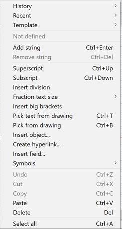
The  Add string and
  Delete string commands are used to edit the number of leader landings. If a simple note is used, these commands control the presence of text below the landing.
NOTE The following hotkeys are available for the Add string command:
Ctrl+Enter – adds a landing below the selected landing;
Shift+Enter – adds a landing above the selected landing.
Right-click in the text field and choose the required menu item:
When you open the context menu on the leader arrow (without selecting the leader), a dialog box for selecting the arrow type will appear:
To create a mechanical note:
The Show dialog before inserting the object option is enabled
1. Run the command.
2. In the Mechanical note dialog box, select the required leader options.
3. Enter the required text into the text fields.
4. Click OK.
5. Specify a point on the object to which the leader arrow will be directed.
6. In the command line or the context menu, select the type of leader line arrow:
None – Creates the extension line without an arrow.
Arrow – Creates the extension line with an arrow.
Point – Creates the extension line with a point.
7. Select an option and specify the leader position on the drawing.
The Show dialog before inserting the object option is disabled
1. Run the command.
2. Specify the point on the object to which the leader arrow will be directed.
3. In the command line or the context menu, select the type of leader line arrow:
None – without an arrow;
Arrow – with an arrow;
POint – with a point.
4. Place the leader landing on the drawing.
5. In the Mechanical note dialog box, select the required leader parameters.
6. Enter the required text into the text fields.
7. Click OK.