
 De
De  Es
Es  Fr
Fr  Pt
Pt 

-
-
-
-
-
-
-
-
-
-
-
-
-
-
-
-
-
-
-
-
-
-
-
-
-
-
-
-
-
-
-
-
-
-
-
-
-
-
-
-
-
-
-
-
-
-
-
-
-
-
-
-
-
-
-
-
-
-
Managing Dependencies
-
-
-
-
-
-
-
-
-
Managing Dependencies
 Main menu: Mechanical - Standard parts >
 Add constraint.
Ribbon: Mechanical - Library >Add constraint.
Toolbar: Add constraint ( "Standard parts").
 Command line: MCCONSTRAINT.
In the dialog box Constraints:
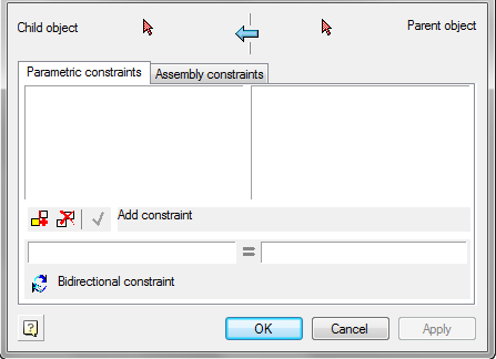
In the dialog box set parametric and assembly (geometric) dependencies between database objects.
The window is divided into two parts:
Left - The child
Right - The parent object
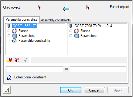
Use
 1-selected object and 2 were selected to the choice made in the drawing, respectively subsidiary and parent objects. After selecting an object in the corresponding half of the window, a list of parameters of the object, which includes:
- Property name
- List surfaces (work surfaces)
- The list object's parameters
- List of installed parametric relationships
- List of installed assembly constraints
On two tabs depending Parametric and Assembly constraints established relationship between parent and child objects.
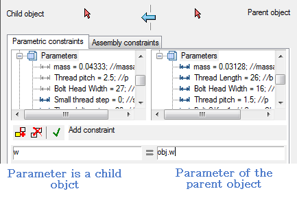
Parametric dependence connects the parameters of objects.
Assembly dependence binds workplanes objects.
Button  New dependency. Allows you to create a new dependency
Button
 Delete dependency. Deletes the selected list dependence
When adding or editing button is activated depending
 Save dependence, which allows you to save your changes.
Installing the parametric dependence
When installing the parametric constraints is associated parameters are recorded in the corresponding input fields located below the list object's parameters. Selecting the link parameters by double-clicking on the corresponding parameters in the list.
Installing assembly according
To install the switch assembly according to the tab Assembly constraints.
Choose binding surface by double-clicking on the appropriate working plane from the list.
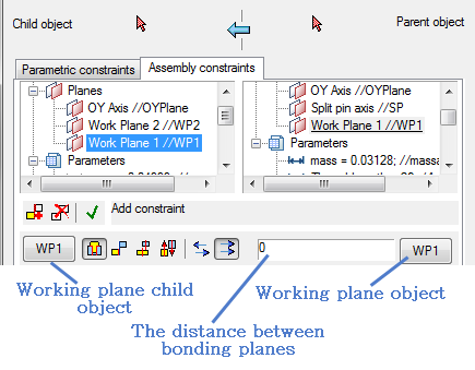
Selecting the plane can also be done visually in the drawing by clicking labelled plane and the linked marker indicating the working plane of the object.
The choice of method depends overlay using the buttons at the bottom:
 Axial and surface alignment
 Surface alignment
 Combination axis
 Direction
Choose mutual orientation related planes using the buttons:
 Counter-directional
 Codirectional
Button
 Bidirectional constraint. Enables two-way relationship in which a related parameter or surface of the parent object changes with appropriate changes to the child object.