

 De
De  Es
Es  Fr
Fr  Pt
Pt 

Main Options Tab
The tab is intended to set the nanoCAD main parameters.
Common settings
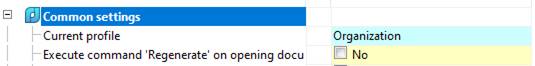
Current profile
Layer profiles are designed to organize the work of various departments of the enterprise on one drawing file. At the same time, each user works with his own group of layers, controlling their visibility by means of nanoCAD.
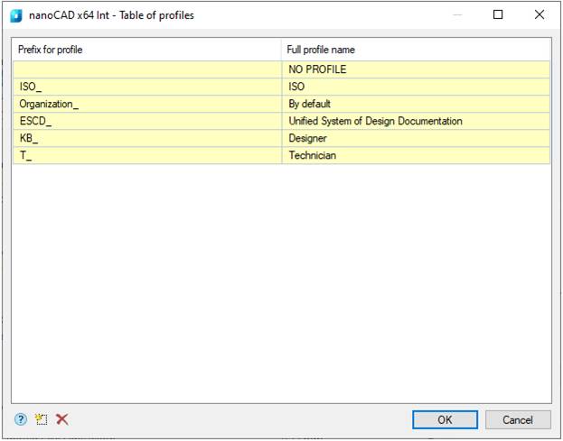
Since the drawing design depends on the settings for the placement of design elements by layers and the current profile of the drawing, then for each type of object you need to set the option of placement on the corresponding layer in the settings (for example, for leaders, the Leaders layer is set).
Depending on the current profile, a prefix will be added to the layer name.
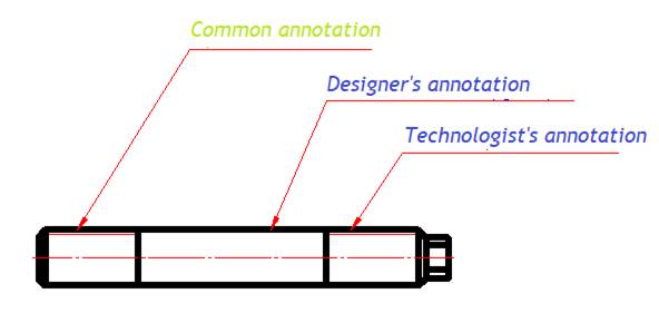
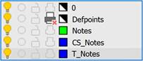
Thus, you can group layers created by users with the same profiles (for example, layers of objects built by designers - by the “KB” prefix, and by technologists - by the “T” prefix).
Perform the Refresh command when opening a document
The Refresh command is performed at each opening of a document (see Refresh command).
Save proxy-objects with graphics
Enables or disables saving proxy objects with graphics.
Line types
Standard nanoCAD objects are displayed with line types provided by GOST 2.302. Line thickness and color parameters are included in the general settings section of the Linetypes group.
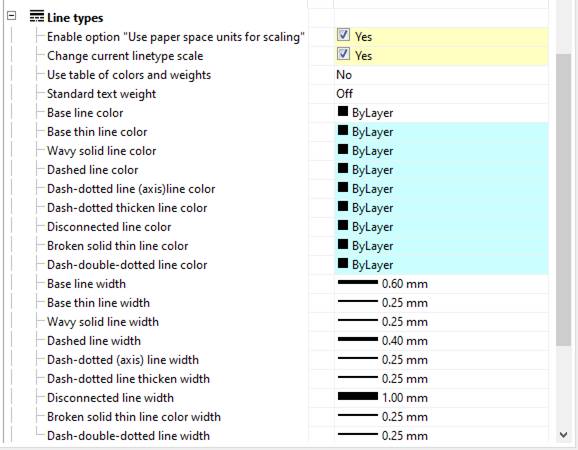
Automatically disable the “Use paper space units for scaling” option
When this option is enabled, while switching between layouts (or from model to layout), the Use paper space units for scaling option, located in the Linetypes dialog, will be reset.
Change current linetype scale
Enables or disables the scaling of linetypes in standard objects when their scale is changed. When the setting is enabled, inserted design elements and database objects are automatically scaled in accordance with the scale of the Scale toolbar.
Use table of colors and weights
Enables or disables the use of color and weights table. If the setting is enabled, you can use standard colors from the table. The Compatibility mode value is used when working with documents created in earlier versions of nanoCAD.
Standard text weight
Standardizes the amount of text weight for all texts, included in the design elements (except for sizes and texts) in a document, relative to the selected line weight:
· Disabled – text weight is equal to line weight;
· 1/10 – text weight is equal to 1/10 of line weight;
· 1/14 – text weight is equal to 1/14 of line weight.
Line color and width
This group of settings assigns the design option for certain types of lines.
Edit

Decimal delimiter correction
Controls the way to automatically replace the decimal delimiter character:
· Do not correct decimal delimiter – does nothing with the delimiter.
· Use dot “.” as decimal delimiter – automatically replaces the delimiter with a dot; an option for programs that accept only a dot.
· Use system locale decimal delimiter – decimal delimiter from OS localization settings is used.
Create and activate standard text and dimension styles in new documents and when changing standards
Controls the creation of standard styles. The default is Yes. Setting this parameter to No allows you to create new documents without predefined standard styles.
Explode Block References under drawing design elements
· Yes – to overlap nanoCAD by objects, nanoCAD blocks are split.
· No – to overlap nanoCAD by objects, nanoCAD blocks are masked (WIPEOUT).
Enable enhanced grips
When this function is enabled, additional nanCAD grips are displayed on the objects, for example: “Flip”, “Insert leader line”, etc.
Set associativity during insertion of objects
The setting is enabled by default. When it is disabled, the snap of inserted objects to primitives is not active.
For example, if the setting is enabled, when you set dimensions on a line, the dimension will be associated with the line. When you change the line, the dimension will change:
If the setting is disabled, only the line will change:
Use localized abbreviations of command keywords
Allows or denies the use of abbreviations for the command keywords described in the file with the .pgp extension and located in the nanoCAD installation folder.
Highlight color
The highlight color for primitives when it is required to specify them. For example, line highlighting when specifying for dimensioning.
Automatically switch keyboard layout to local language
When you call dialogs with fields in nanoCAD, the local layout is automatically turned on.
Show rectangle around objects
Controls the display of the bounding box around objects and nanoCAD blocks. When this option is enabled, scaling is disabled by Shift+RMB.
Automatically turn on snaps: Nearest, Endpoint, Quadrant, Center, Intersection
Temporary turns on the listed snaps when some nanoCAD command work.
· If the option is disabled, some dimensioning modes will not work.
· If the option is disabled, the Direction toolbar will not work correctly.
· If the option is disabled, placement along the leader line, slope symbols, symbols of base and, possibly, other objects will not work.
To show the toolbar “Direction” automatically
Controls display of the Direction toolbar, which appears when inserting database objects and in a number of other commands.
Scale dimensions
Yes value. The global scale set in the Dimension Styles on the Fit tab is replaced by the design scale.
No value. The global scale is not changed.
|
|
Note |
|
If the design scale differs from the global scale value, then a dimension style override will be created. |

Scale texts
Applicable for the inserted text.
Yes value. When you change the design scale using the Scale toolbar, the Height parameter changes proportionally in the Text Format dialog for multiline text and in the command line for single line text.
No value. When you change the design scale using the Scale toolbar, the Height parameter does not change.
The platform saves the value of the last entered text height. When this option is enabled, changing the design scale proportionally changes the saved height value. The new text will have the modified height.
Example: Initial data – text height 10, scale 1:1. Change the scale to 1:15. The height of the new text will be 150.
Scale hatches
Applicable for the new hatches.
Yes value. When you change the design scale using the Scale toolbar, the Scale parameter in the Hatch changes proportionally.
No value. When you change the design scale using the Scale toolbar, the Scale parameter in the Hatch dialog does not change.
The platform saves the value of the last entered hatch height. When this option is enabled, changing the design scale proportionally changes the saved height value. The new hatch will have the modified height.
Example: Initial data – hatch height 10, scale 1:1. Change the scale to 1:15. The height of the new hatch will be 150.
Scale .dwg tables
The setting is used when creating a dwg table. If the setting is disabled, the table is inserted with the dimensions specified in the table creation dialog. If the setting is enabled, the size of the inserted table changes in proportion to the design scale.
Scale Block References
· Yes – the block is scaled when the symbol scale (design scale) changes.
· No – the block is not scaled when the symbol scale (design scale) changes.
Unlike design objects, which inherit the current symbol scale when created, a block has a symbol scale of 1:1 after insertion into a drawing.
Ignored layers
Specifies nanoCAD layers for which primitives located on them will not be overlapped by nanoCAD objects.
Clicking on the ellipsis will open the Ignored layers dialog for editing the list of layers:
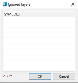
The dialog menu allows you to add a layer and enter it manually, delete a line with a layer, or select a layer from those available in the drawing.
Unplotted layer
Specifies the layer on which nanoCAD objects excluded from plot (group markers, non-printable markers, mark anchors, shown dependencies) are placed.
Mini-toolbar for viewports
Controls the display of special nanoCAD mini-toolbar 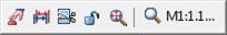 , by the right click inside the viewport. If the option is disabled, the standard nanoCAD context menu will be called.
By double-click
Establishes editing method for design objects by double-click. The setting has four parameters:
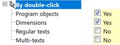
Program objects –
when this option is enabled, double-clicking on leaders and tables will open dialog boxes for editing the object; when this option is disabled, the Properties bar (PROPERTIES command) will be displayed;
Dimensions – when this option is enabled, double-clicking on a dimension will open the Edit Dimension dialog box; when this option is disabled, the command for editing multiline text will be displayed. The method for editing sub-dimension text (the second line of the dimension text) is configured using the Multi-Texts parameter;
Regular texts – when this option is enabled, double-clicking on a single-line text will open the Text Settings dialog box; when this option is disabled, the command for editing a single-line text will be displayed;
Multi-texts – when this option is enabled, double-clicking on a multi-line text will open the Text Settings dialog box; when this option is disabled, the command for editing a multi-line text will be displayed.
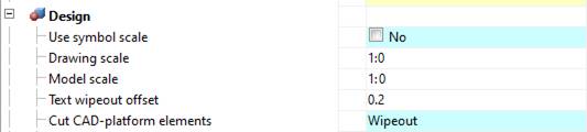
Design
ESCD Standard:
SPDS Standard:
Use symbol scale
Change the scaling type:
· Enabled – Scale of symbol.
· Disabled – Scale of dimensions.
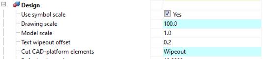
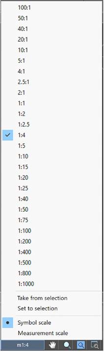
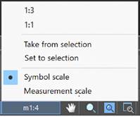
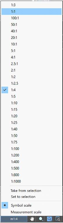
Drawing scale
Sets the default scale of design elements and the scale of geometry linetypes. By default:
· Standard 1:100;
· Standard 1:1.
|
|
Note |
|
The scale of dimension line types is reserved and always defaults to 1. |
Model scale
Sets the default measurement scale. The displayed value, which is set when setting dimensions, increases in direct proportion to the scale value. For example, when setting the dimension of a 10 mm segment with the measurement scale 1:10, the displayed value will be 100.
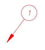
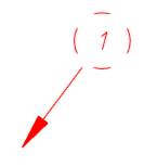
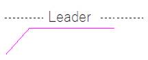
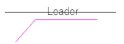
Text wipeout offset
Sets the default offset of the geometry mark from the text. At large sizes the background overlaps the geometry:
|
0.2 |
1 |
|
|
|
Cut CAD-platform elements
Controls the overlap of nanoCAD primitives by design elements. Is reverse-acting. Acceptable values: No, Cut, Wipeout.
Wipeout – closes a primitive.
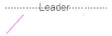
Cut – cuts a primitive section. When deleting or moving, the cut primitive returns its state.
No – does not overlap a primitive.
Default Tab
Allows you to set the default tab value in millimeters.
Font size for fractions
Sets the font size for fractions. Acceptable values: One step less, Equal to the main.
List of drawing scales
Sets the list of scales. Valid values: Standard only
(scales according to the Standard), Document only (scales read from the document), All (scales according to the Standard are added to the scales from the document).
To create custom scales in the document, use the Edit Drawing Scales (SCALELISTEDIT) command.
|
Standard only |
Document only |
All |
|
|
|
|
Default text style
Sets the default text style. Acceptable values: GOST 2.304, Standard.
Notifications
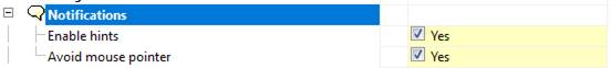
Enable hints
Enables or disables the display of hints in the notifier. The option does not apply to a notification with the Error status.
Avoid mouse pointer
Enables or disables the mode of automatic displacement of hints not to interfere with the selection of objects.
Hot keys
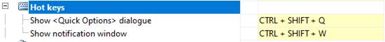
Hot keys are assigned to open Quick Options and Notifications (notifier) dialog boxes.
Databases access
The database includes, in addition to standard elements, table and format templates, bolted assembly templates, groups and markers, as well as examples and other custom elements. The choice of a specific database is determined by configuration of the path to the data source.
Data Source – a path to the file of the standard objects database.
|
|
Attention |
|
When placing the nanoCAD database in a network resource, it is necessary to allow all users to write to the folder where the base is located. In this case, the file with the database itself can be read-only (then users will not be able to change the contents of the network database). |

Clicking on the ellipsis will open the Select Data Source dialog:
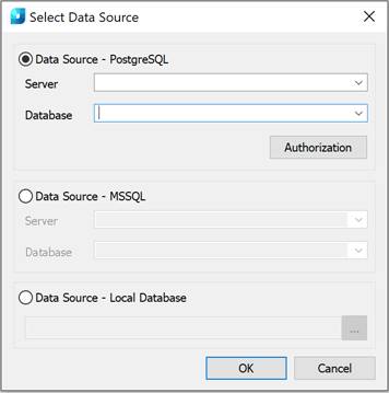
nanoCAD provides for work with both local databases and databases on PostgreSQL and MSSQL servers.
When using server database, it is necessary to specify the server name in the Server field (along with the name of the SQL database server). For example: SERVER or SERVER\SQLEXPRESS.
In the Database field, it is necessary to specify the name of database to which connection is made.
The PostgreSQL data source may require authorization. By default, the database is logged in as the standard user mclogin. To log in to the database with additional rights or as an administrator, you must log in.
To log in to PostgreSQL:
1. Click the Authorization button. The Authorization dialog box will open.
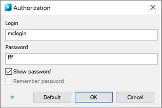
2. In the dialog box, specify the user and the password.
3. Click OK to confirm. The specified data will be used for further connections.
If the local database is used, it is necessary to select the Database source - PostgreSQL switch, and then specify a path to the database file.
For x32 computers, *.mcs (MS Access) files are used as a local database.
For x64 computers, *.mdf (LocalDB, for Windows 7 and above) files are used as a local database.
The necessary drivers are installed automatically when installing nanoCAD.
|
|
Note |
|
Database access settings are interface settings. Problems can occur when using disk compression with connection to local databases (for 64-bit versions). |