nanoCAD Platform Help

Linetype Editor

Edit Linetype

In the Linetype Manager you can edit the selected line type or create a new one using the built-inLinetype Editor:

 CAD drafting Linetype Editor 0

Parameters:

Description of line types

Description of line types is shown.

Buttons

CAD software Linetype Editor 1 

Add dash

Adds a new element to the line.

CAD drawing Linetype Editor 2 

Delete dash

Deletes an element from the line.

CAD drafting Linetype Editor 3 

Move dash up

Moves one element up.

CAD software Linetype Editor 4 

Move dash down

Moves one element down.


CAD drawing Linetype Editor 5

Elements are selected in the Common section.

There are the following options in the drop-down list:

·         Dash

·         Text

·         Shape

CAD drafting Linetype Editor 6

An element’s value is shown in the Geometry section.


To edit a line type:


1.    Select a line type in the Linetype Manager.

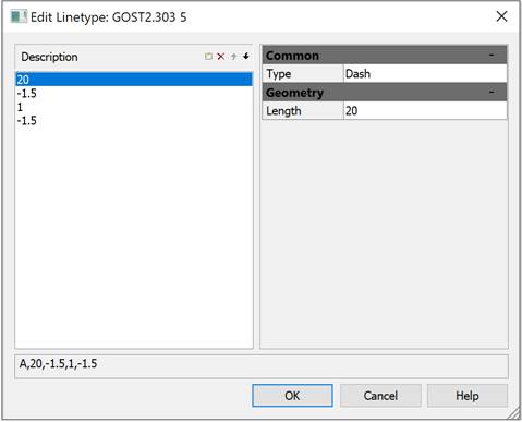
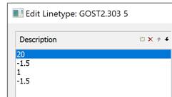
2.    Click the CAD software Linetype Editor 7 Edit linetype button to start the built-in Linetype Editor. There is a description of the selected line type in the Dashes field:

CAD drawing Linetype Editor 8

3.    Select an element and enter its new value in the Length field of the Geometry section.

note: When you specify a positive value, a dash is drawn, when you specify a negative value, a space is drawn, when a value is zero a point is drawn.


note: The length of the first element must be greater than or equal to zero, i.e. the dash or point must be drawn first.


4.    To display a new value, press ENTER or just click.

5.    To add a new element, click the CAD drafting Linetype Editor 9 Add dash button. A new element is added to the end of the list and a zero value is assigned to it by default.

6.    Specify a new value for an added element in the Length field of the Geometry section. To display a new value press ENTER.

7.    Click OK to close the Edit Linetype dialog box.

8.    Click OK to close the Linetype Manger dialog box.

To add text to a description of a line type:


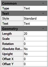
1.    In the Type field select the Text option:

CAD software Linetype Editor 10

2.    In the Style field of the Text section, select a text style from the drop-down list. In the Text field enter symbols, specify parameters in the Geometry section:

CAD drawing Linetype Editor 11

3.    Click OK to close the Edit Linetype dialog box.

4.    Click OK to close the Linetype Manger dialog box.

To add a shape to a description of a line type:


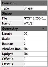
1.    In the Type field select the Shape option:

CAD drafting Linetype Editor 12

2.    Select a shape name from the drop-down list in the Name field and a shape file in the File field of the Shape section. Specify required parameters in the Geometry section:

CAD software Linetype Editor 13

3.    Click OK to close the Edit Linetype dialog box.

4.    Click OK to close the Linetype Manger dialog box.

Creation of a New Linetype

A new line type is created on the base of an existing one:


1.    In the Linetype Manager select a line type.

2.    Click the CAD drawing Linetype Editor 14 New linetype button. The new row has a default name – Linetype1 appears.

3.    Click Linetype1 and enter a new name.

4.    In the Description field enter information about the line type.

5.    Click the CAD drafting Linetype Editor 15 Edit linetype button.

6.    Change the parameters in the Edit Linetype dialog box.

7.    Click OK to close the Edit Linetype dialog box.

8.    Click OK to close the Linetype Manager dialog box.

Brief Description of the Procedure for Creating Custom Linetypes

You can view and, if necessary, edit the content of GOST 2.303-68.lin file in any text editor that saves data in ASCII format:

;;

;; linetypes by GOST 2.303-68

;; 


*GOST2.303 3,Solid wavy ~~~~~~~~~~~~~~~~~~~

A,0.001,[WAVE,GOST 2.303-68.shx],-26

*GOST2.303 4,Dashed __ __ __ __ __ __ __ __ __

A,5,-2,0

*GOST2.303 5,Dash-dot thin ____ _ ____ _ ____ _ ____ _

A,20,-1.5,1,-1.5

*GOST2.303 6,Dash-dot theckened ___ _ ___ _ ___ _ ___ _ ___ _ ___

A,8,-1.5,1,-1.5

*GOST2.303 8,Solid thin kinks ---'\---'\---'\---'\---'\---

A,40,[BREAK,GOST 2.303-68.shx],-8

*GOST2.303 9,Dash-dot with two dots __..__..__..__..__..__..__..__.._

A,20,-1.5,1,-1.5,1,-1.5

Lines that start with a semicolon (;) character are comments.

Description of a linetype consists of 2 lines: the first line contains the linetype name and a short description, the second line specifies the linetype outline.

*GOST2.303 5,Dash-dot thin ____ _ ____ _ ____ _ ____ _

A,20,-1.5,1,-1.5

An asterisk is placed before the linetype name. The name should be unique.

*GOST2.303 5

The linetype name is separated from a short description by a comma.

*GOST2.303 5,Dash-dot thin ____ _ ____ _ ____ _ ____ _

A brief description consists of a text part explaining the purpose of the linetype (for example, the explanation Dash-dot can be changed to the following: To draw center lines). The description often includes a sequence of text characters (dashes, spaces, dots, etc.) that visually resembles this line. The description can be up to 47 characters long. The description is optional and can be omitted. If there is no description, no comma is placed after the linetype name.

The second line containing the linetype description begins with the character A, which defines the type of alignment.

Further, separated by commas (without spaces), write the linetype elements that specify the line style.

A,20,-1.5,1,-1.5

As elements of the linetype outline, the following can be used:

·         zero – specifies a dot construction;

·         positive decimal numbers – specify the construction of dashes (a number value determines the dash length in drawing units);

·         negative decimal numbers – specify the construction of spaces (a number value determines the space length in drawing units);

·         text objects;

·         embedded shapes stored in form files.

Linetypes described by dashes, dots and spaces are called simple. The complex linetypes include the ones described by text objects and embedded shapes. Linetypes that include text objects and embedded shapes are used in utility network signs, in topographic symbols, and so on.

In the GOST 2.303-68.lin file the linestypes *GOST2.303 4, *GOST2.303 5, *GOST2.303 6 and *GOST2.303 9 are simple, the linetypes *GOST2.303 3 and *GOST2.303 8 are complex, because their descriptions use the embedded shapes WAVE and BREAK.

Alignment type A determines the condition according to which lines should begin and end with dashes, i.e. the value that determines the length of the first segment of the line should be greater than or equal to zero.

In order to better understand what alignment is and how it works, consider an example of drawing a line segment from point 1 to point 2 using Dash-Dot linetype. The program will construct a segment in such a way that it starts at point 1 and ends at point 2 with dashes. If necessary, the first and last dashes can be lengthened to meet the alignment condition. For a short segment, if it does not contain even one link long_dash-space-short_dash-space, the program will draw one dash (continuous line).

The linetype description line should not exceed 80 characters.

For each linetype it is possible to define no more than 12 elements.

In the linetype description, it is enough to specify one repeating fragment (link). For example, for the Dash-dot linetype such fragment is the link long_dash-space-short_dash-space.

The format for determining a simple linetype is:

A,Length1,Length2,Length2,…

Text objects are generally described in a complex linetype definition in the following format:

[”Text”,Style,Scale,Rotation_angle,Offset_X,Offset_Y]

The format for writing the embedded shape in the definition of a complex linetype:

[Name,File]

or

[Name,File,Scale,Rotation_angle,Absolute_rotation,Offset_X,Offset_Y]

Parameters:

Option

Brief information about the option

Value examples

Length

The length of dash or space in drawing units.

Values can be positive or negative numbers:

20, -1.5, 0.001

Value 0 – constructing a point.

Text

Text symbols used in a complex line.

The option is used to describe a text object.

Any set of text symbols:

C, D, UK, W1, K1.

Style

The name of a text style.

The option is used to describe a text object.

The default style is

Standard

A style is available for selection in the drop-down list

GOST 2.304

Name

Shape name.

The option is used to describe an embedded shape.

Mandatory parameter – if it is absent, the linetype is not defined.

If there is no from in the specified file (File option), the line is constructed without a shape.

WAVE, BREAK, LINE FEED

File

The name of compiled (*.shx) rile containing a shape definition.

The option is used to describe an embedded shape.

Mandatory parameter – if it is absent, the linetype is not defined.

Is there is no form file, a line is drawn without a shape.

GOST 2.303-68.shx

Scale

The scale factor by which the height of the text style or the original height of the shape is multiplied.

The format of the entry in the linetype description:

S=value.

If the height of the text style or the initial height of the shape are equal to 0, then the specified value of the S = parameter is used as the height.

S=3, S=0.1, S=.1

Rotation angle

The angle of rotation of a text object or embedded shape relative to the line direction.

The format of the entry in the linetype description:

R=value.

It is allowed not to specify the parameter, in this case its value is assumed to be 0.

R=0, R=30, R=-90

Absolute rotation angle

The angle of rotation of a text object or embedded shape relative to the coordinate origin, i.e. all text objects or all shapes rotate the same regardless of their position relative to the line.

The format of the entry in the linetype description:

A=value.

It is allowed not to specify the parameter, in this case its value is assumed to be 0.

A=0, A=45, A=-30

Offset by X

The offset of a text object or embedded shape by X axis directed along the line.

The format of the entry in the linetype description:

X=value.

The parameter X=0 is set when describing a continuous line containing text objects or embedded shapes.

It is allowed not to specify the parameter, in this case its value is assumed to be 0.

The parameter S= does not affect the X offset.

X=5, X=-2.5, X=0.01

Offset by Y

The offset of a text object or embedded shape by Y axis perpendicular to the line.

The format of the entry in the linetype description:

Y=value.

The parameter Y=0 is set when describing a complex line containing text objects or embedded shapes without offset by Y.

It is allowed not to specify the parameter, in this case its value is assumed to be 0.

The parameter S= does not affect the Y offset.

Y=0.01, Y=-3.5, Y=7

Linetypes examples:


1.    Definition of a simple linetype Dash-dot thin:

*GOST2.303 5,Dash-dot thin ____ _ ____ _ ____ _ ____ _

A,20,-1.5,1,-1.5

specifies the construction of a line that starts with a dash of 20 drawing units length followed by a space of 1.5 drawing units, then a dash of 1 drawing unit is built, then again a space of 1.5 units. This fragment (link) is repeated throughout the segment, ending at the end point with a dash of 20 drawing units:

CAD software Linetype Editor 16

2.    Definition of a complex linetype Funny, containing text symbols 8 and ):

*Funny,Example of a custom linetype

A,10,-10,0.001,["8)",Standard,S=5,R=-90,X=-3,Y=3],-10

CAD drawing Linetype Editor 17

3.    Definition of a complex linetype Arrow1 containing text symbols < and >:

*Arrow1,Single arrow

A,0.001,["<",Standard,S=5,Y=-2.5],25,[">",Standard,S=5,X=-2.5,Y=-2.5],-20

CAD drafting Linetype Editor 18

4.    Definition of a complex linetype Arrow2 containing text symbols < and >:

*Arrow2,Double arrow

A,0.001,["<",Standard,S=5,Y=-2.5],0,["<",Standard,S=5,X=3,Y=-2.5],25,

[">",Standard,S=5,X=-2.5,Y=-2.5],0,[">",Standard,S=5,X=-5.5,Y=-2.5],-20

CAD software Linetype Editor 19

5.    Definition of a complex linetype GOST2.303 8 containing the embedded shape BREACK:

*GOST2.303 8,Continuous jogged line ---'\---'\---'\---'\---'\---

A,40,[BREAK,GOST 2.303-68.shx],-8

CAD drawing Linetype Editor 20

6.    Definition of a complex linetype A1 containing an embedded shape LEG_SIGN1:

*A1,Example of a custom linetype

A,10,-20,0,[LEG_SIGN1,CS_Gost2304.shx,S=5,R=180,X=-5.5,Y=2.5]

CAD drafting Linetype Editor 21

7.    Definition of a complex linetype Dashed 14-4 containing embedded shapes ARROWFILL, CIRCLEFILL_IN and CIRCLEFILL_OUT:

*Dashed 14-4,Dashed line. under linear object  <|---O---|>

A,0.01,0,[ARROWFILL,styles.shx,S=0.1,R=180,X=0.7],7,0,[CIRCLEFILL_IN,styles.shx,

S=0.1],0,[CIRCLEFILL_OUT,styles.shx,S=0.1],7,0,[ARROWFILL,styles.shx,S=0.1,X=-0.7],-4

CAD software Linetype Editor 22

Info: NanoCAD is a user friendly, cheap, and yet powerful, CAD software tool for Windows, that allows an outstanding user experience by providing top-level performance, full capability, a classic interface and native.dwg format support. nanoCAD has been built to deliver design and project documentation for all industrial purposes. nanoCAD includes a full suite of basic and advanced CAD tools for 2D/3D design and creating industry-standard DWG-compatible CAD files. Our program ensures creative, collaborative and customizable features to boost your efficiency, and includes several API's, allowing anything from routine task automation to complex CAD app development. You may download nanoCad for free, using the links below, and buy later, in case you like it.