

 De
De  Es
Es  Fr
Fr  Pt
Pt 

-
-
-
-
-
-
-
-
-
-
-
-
-
-
-
-
-
-
-
-
-
-
-
-
-
-
-
-
-
-
-
-
-
-
-
-
-
-
-
-
-
-
-
-
-
-
-
-
-
-
-
-
-
-
-
-
-
-
-
-
-
-
-
-
Level mark on plane
-
-
-
-
-
-
-
-
-
-
-
-
-
Level mark on plane
 Main menu: Construction - Level marks >
 Level mark on plane.
Ribbon: Construction - Symbols >Level mark on plane.
Toolbar: Level marks >Level mark on plane.
 Command line: SPPLLEVEL.
Procedure
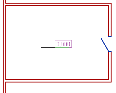
1. Call the command "Level mark on plane".
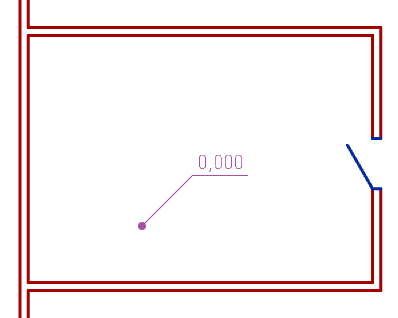
2. Specify the insertion point for the first level mark in the drawing. The "Plane elevation marks" dialog will open.
3. In the "Plane elevation marks" dialog box, enter a level value. Determine the number of extension lines. Select the appearance of the level mark: framed, underlined, or text only.
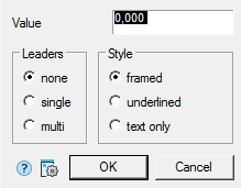
4. Confirm your selection with the "OK" button.
5. Specify the extension lines (if you selected the value of the extension lines "single" or "multi", to complete the selection of lines, press the "Esc" key).
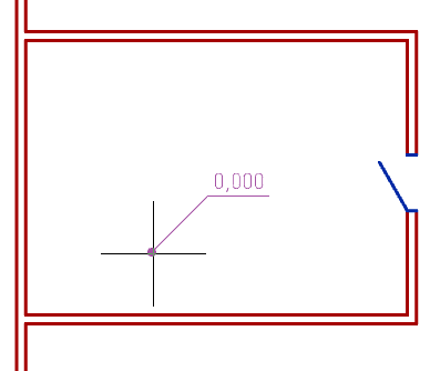
6. The command works in cyclic insert mode. Insert the required number of level marks into the drawing. End the loop command with the "Esc" key.
Grips
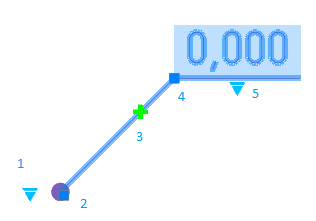
1. Drop-down arrow type selection grip.
2. Leader line position grip.
3. Leader line grip.
4. Grip for changing the position of the shelf.
5. Drop-down grip for selecting the type of drawing.