
 De
De  Es
Es  Fr
Fr  Pt
Pt 

-
-
-
-
-
-
-
-
-
-
-
-
-
-
-
-
-
-
-
-
-
-
-
-
-
-
-
-
-
-
-
-
-
-
Interface of the Table Editor Dialog
-
-
-
-
-
-
-
-
-
-
-
-
-
-
-
-
-
-
-
-
-
-
-
-
-
Interface of the Table Editor Dialog
The full table editor (the Table edit dialog box) when the Program objects parameter is set to Yes in the Edit – By double-click section of the Main options tab of the nanoCAD Design Settings (PARAMS) dialog box, can be opened:
· by double-clicking on the frame inserted into the drawing table,
· by right button clicking on the table frame (the full table editor will be opened if you press CTRL).
The edit and fedit commands allow you to open the Table edit dialog box, it does not matter what value is chosen for the Program objects option.
You can also open the Table edit dialog by selecting the table, clicking the right button and selecting the Edit command in the context menu.
The Table edit dialog box:
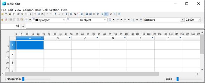
The dialog box contains:
· standard pull-down menus
 ;
;
· tool palette buttons

· rulers with sliders allowing column width or row height to be quickly adjusted
· the cell grid with name headers
 .
.
· status bar with transparency and scale sliders.
Each table section has a header:
· First page header
· Header
· Last page header
· Report header
· Report template
· Report
· Report sum
· First page footer
· Footer
· Last page footer
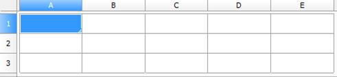
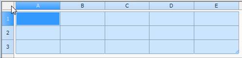
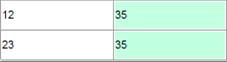
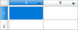
Names (addresses) of table cells are fully equivalent to those used in MS Excel: columns are marked alphabetically (A, B, C, D, ... , Z; AA, BB etc.) while rows are marked with ordinal numbers.
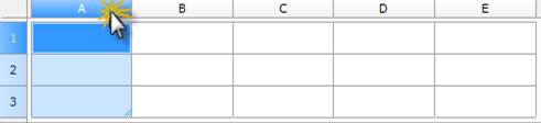
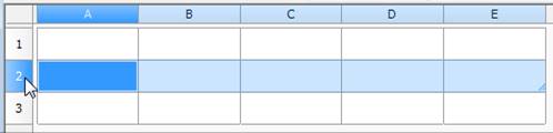
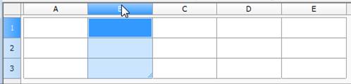
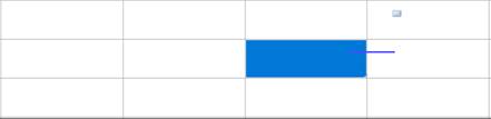
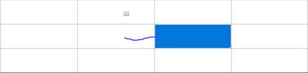
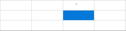
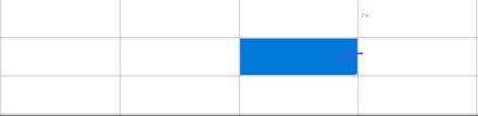
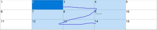
When you left-click on a row or column name, it is selected:
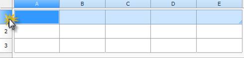
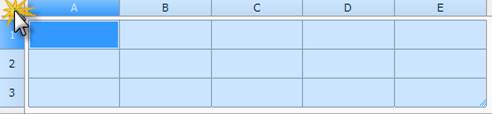
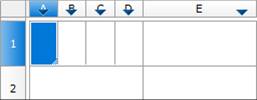
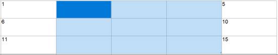
To select the entire table, click on the rectangle at the intersection of the columns with the names of the rows and columns:
The CTRL+MOUSE WHEEL SCROLL key combination changes the table scale.
The CTRL+MOUSE WHEEL PRESS key combination sets the table scale to the default.
The CTRL+ALT+UP ARROW key combination moves a row up.
The CTRL+ALT+DOWN ARROW key combination moves a row down.
The CTRL+ALT+LEFT ARROW key combination moves a column to the left.
The CTRL+ALT+RIGHT ARROW key combination moves a column to the right.
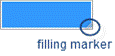
Filling of adjacent cells with data
To accelerate the data input in the table, it is possible to use the function of automatic data filling. The table editor can automatically continue a line of numbers, number combinations and text with a set pattern. By selecting several cells and dragging the filling marker, it is possible to quickly fill in the data lines with the different types.
Filling cells with sequences of numbers or combinations of numbers and text with a set pattern:
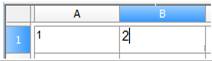
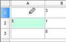
1. Select the first of the filled cells:
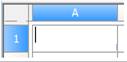
2. Enter the initial value for the values line:
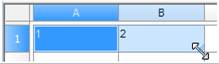
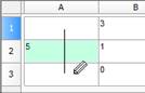
3. Enter a value in the following cell to set the filling pattern:
4. Select the cell or cells containing the initial values:
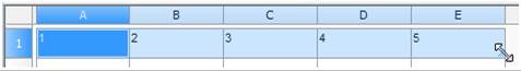
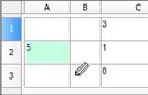
5. Drag the filling marker over the range with which it is necessary to fill:
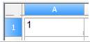
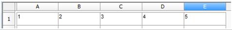
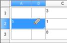
6. The cells will be filled with the set sequence of numbers:
Examples:
1. If the sequence 1, 2, 3, 4, 5... is required, you need to enter the values 1 and 2 in the first two cells. If the sequence 2, 4, 6, 8… is required, enter 2 and 4.
2. If the sequence 2, 2, 2, 2… is required, the second cell can be left empty.
3. The sequence filling proceeds as shown in the table below:
|
Initial value |
Line extension |
|
1, 2, 3, ... |
4, 5, 6, ... |
|
First period, Second period, … |
Third period... |
|
Article 1, Article 2, … |
Article 3... |
|
|
Attention |
|
To fill in an increasing order, drag the marker down or to the right. To fill in a decreasing order, drag the marker up or to the left. |

Use the autofilling to continue lists containing the values from collections (main menu/rows/user sorting).
|
|
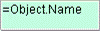
Cell containing an expression. |
|
|
Not edited cell, for example, in report. |
|
|
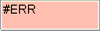
Cell with a mistake in expression. |
|
|
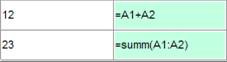
Cell containing data of report section. |

File
Open file… – loads table data from a file. The following files are available for loading: *.tbl, *.dat, *.mdb (only for 32-bit Windows), *.txt, *.csv, *.xml, *.xls, *.xlsx, *.sxc, *.ods. When selecting an Excel file, only the first sheet of the book is inserted.
Open base – opens the standard elements dialog for selecting a table saved in the database.
Save as file… – writes the table to an external file *.dat, *.txt, *.cvs, *.xml, *.xls.
Save to base… – writes the table to the element database.
Import from Excel – the command transfers the results of tabular data calculations from an open MS Excel workbook. The contents of the active sheet or the selected range of cells are transferred.
Export to Excel – the command is designed to transfer tabular data to MS Excel. After clicking the button, the Conversion Options dialog opens. After setting the options, a new Excel workbook is opened and all table data is transferred to it, preserving the cell formatting set in the table.
Close ALT+F4 – saves changes and closes the editor
Close without saving – closes the editor without saving changes.
Edit
Undo – undoes the last action.
Redo – repeats the last undone action.
Cut – cuts data from the selected cells to the clipboard.
Copy – copies data from the selected cells to the clipboard.
Paste – pastes data from the clipboard.
Pencil – splits cells into several by constructing additional borders.
Select material... – opens the Material dialog box.
Auto calculation – controls the automatic recalculation of table cell values. The auto recalculation mode is enabled by default.
Recalculate F5 – recalculates data in the table after editing cell values or correcting formulas.
Auto reports – controls the automatic report recalculation mode. The mode is enabled by default.
Update reports – updates the report.
Syncronize – updates the table with data from a linked file. Available if the table was loaded from a file. For correct synchronization, the changed data in the file must be previously saved.
View
Show rulers – switch, controls the display of the ruler.

Navigation bar – switch, controls the display of the formula bar.

Show expressions – switch, controls the display of formulas in cells.
|
Enabled |
Disabled |
|
|
|
Formula visualization – switch, controls the display of formulas in cells when the Show expressions switch is enabled.
|
Enabled |
Disabled |
|
|
|
Pan to objects – positions the source report objects in the center of the drawing.
View sorting – controls the display of view sorting buttons. Sorting is intended to make data entry in the spreadsheet editor more convenient and does not affect the state of the table in the drawing. The button has three states:  None,
None,  Ascend,
  Descend. Features of sorting:
· Enabling sorting on one column disables sorting in other columns.
· Rows are sorted as a whole, not just the column.
· Rows are sorted within a section.
· Cell merging is not broken.
· After view sorting is enabled, the vast majority of commands are blocked. Allowed: exit, editing single cells, and changing the sorting mode.
Calculator – the command opens the Calculator.
Notebook – the command opens the notebook.
Column
Add column – adds a new empty column after the selected column.
Insert column – adds a new empty column before the selected column.
Delete column – deletes the selected column.
Hidden – switcher, hides the column. The column is displayed in the editor, but is not displayed in the drawing.
Properties... – opens the column properties.
Row
Add row – adds a row below the selected one.
Delete row – deletes the selected row.
Hide row – hides the row. The row is visible neither in the editor nor in the drawing.
Show hidden rows – shows hidden rows. To use the command, select several rows between which the hidden rows are located.
Sort ascend – sorts the table in ascending order relative to the selected column.
Sort descend – sorts the table in descending order relative to the selected column.
Merging and grouping... – opens the Grouping and merging dialog.
Start new page – switch that controls the page break before the selected row.
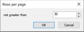
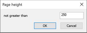
Limit rows per page... – opens the Rows per page dialog, which specifies the maximum number of rows on a page. If there are more rows, a page break is inserted.
Limit page height... – opens the Page height dialog, where the maximum page height is specified. If the page height is greater than the specified one, a page break is inserted.
Single page – the command removes all created page breaks.
Up to down – switch that controls the sequence of data display.
Properties... – opens the row properties.
Cell
Edit F2 – switches the cell to edit mode.
Expression... SHIFT+F2 – opens the Expression builder dialog.
Properties... – opens the Cell Properties dialog.
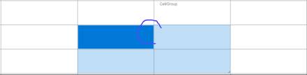
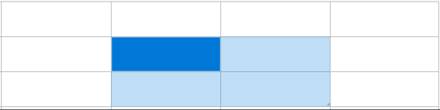
Group – groups the selected cells.
Ungroup – ungroups the selected cells.
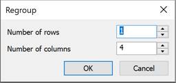
Split... – splits the cell into several rows and columns. When the command is called, the Regroup dialog appears.
Cut – cuts data from selected cells to the clipboard.
Copy – copies data from selected cells to the clipboard.
Paste – pastes data from the clipboard.
Clear – clears selected cells.
Insert table – pastes a range of cells copied from Excel.
Sections
Header of first page – adds a header for the first page.
Header of every page – adds a header for pages.
Header of last page – adds a header for the last page.
Insert Data section – inserts a data section. If the selected cell is in the data section, an empty row is added.
Insert Report section – adds a report section. Used when compiling reports.
Footer of first page – adds a footer for the first page.
Footer of every page – adds a footer for pages.
Footer of last page – adds a footer for the last page.
|
|
Open file |
The button with a black triangle opens access to additional buttons for selecting a data source:
When selecting an Excel file, only the first sheet of the book is inserted. |
||
|
|
Save to file |
The button with a black triangle opens access to additional buttons for selecting the location to save the table:
|
||
|
|
Import table from Excel |
Transfers the results of tabular data calculations from an open MS Excel workbook. The contents of the active sheet or the selected range of cells are transferred. |
||
|
|
Export table to Excel |
Transfers tabular data to MS Excel. After clicking the button, the Conversion Options dialog box opens. After setting the options, a new Excel workbook is opened and all tabular data is transferred to it, preserving the cell formatting set in the table. |
||
|
|
Update table from external source |
Updates the table with data from a linked file. Available if the table was loaded from a file. For correct synchronization, the data changed in the file should be first saved. |
||
|
|
Pan and zoom view to show objects |
Positions in the drawing by the center of the source report objects. |
||
|
|
Cut: |
Copy the selected data into the clipboard and delete from the table. |
||
|
|
Copy: |
Copy the selected data into the clipboard. |
||
|
|
Paste: |
Paste data from the clipboard. |
||


 – Inserts a table from a database.
 – Inserts a table from an external file *.tbl, *.dat, *.mdb (only for 32-bit Windows), *.txt, *.csv, *.xml, *.xls, *.xlsx, *.sxc, *.ods.

 – Write the table to the element database.
 – Write the table to an external file *.dat, *.txt, *.cvs, *.xml, *.xls, *.ods.


|
|
Undo last change: |
Undo last change. |
|
|
Redo last change: |
Redo last change. |


|
|
Move row down: |
Moves the selected row one position down. |
||
|
|
Move row up: |
Moves the selected row one position up. |
||
|
|
Move column left: |
Moves the selected column one position left. |
||
|
|
Move column right: |
Moves the selected column one position right. |
||
|
|
Page division: |
This tool is intended for dividing a table into multiple fragments without losing its integrity. Use this function to split a large table in order to place it on a smaller sheet of paper, while still being able to edit it as a whole. |
||
|
|
Sort ascend |
Sorts rows in ascending order of cell values in the current column (the column of the selected cell). |
||
|
|
Sort descend |
Sorts rows in descending order of cell values in the current column (the column of the selected cell). |
||
|
|
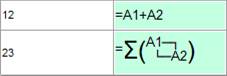
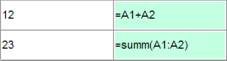
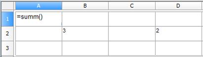
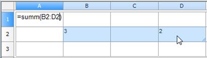
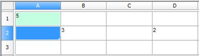
Create summary function |
Summing the contents of selected cells: · Select the cell in which you want to calculate the sum. · Click the
· Select the cells whose contents you want to sum:
· Press Enter to calculate the sum:
|
||
|
|
Open calculator |
Opens the Calculator dialog box. |
||
|
|
Open notebook |
Opens the Notebook dialog box. |
||
|
|
Insert material |
Opens the Material dialog box. |
||
|
|
Special symbol |
Opens a bar for selecting and inserting special characters. |
||
|
|
Recalculate Table: |
This button is used to manually update the calculated cell data after editing reference cell values or altering expressions. |
||
|
|
Automatic calculation: |
Operates a mode of automatic recalculation of the values of the table cells. By default, the automatic calculation mode is included. |
||
|
|
Update reports: |
Click this button to update the report. |
||
|
|
Automatic report update: |
Operates a mode of automatic recalculation of the report. By default, the automatic report update mode is included. |
||
|
|
Select cell style |
Opens a bar to select and apply a style to selected cells. |
||


|
|
|
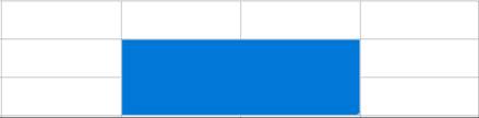
Group selection: |
Merges multiple cells into a single cell. |
|||
|
|
|
Ungroup selected cells: |
Restores the original cells from merged cells. |
|||
|
|
|
Change count of rows and columns: |
Use to change the count of rows and (or) columns in the chosen cells range: · Select one or several cells. · Click the · In the Regroup dialog box that appears, enter the required values for breakdown
|
|||
|
|
|
Split table cells with pencil tool |
Use to insert new cells by manually drawing new grid lines: · Specify the start and end point of a line which will divide each cell that is crossed by it into two:
· Right-click on a cell border to delete this border:
· Click Split table cells with pencil tool button to finish. |
|||
|
|
|
Borders |
Controls the display of borders of selected cells. When you click on the button with a black triangle, additional border display buttons become available:
|
|||
|
|
To set border parameters: · first select the color and/or thickness of the border; · select the border to which you want to apply the specified parameters (using the |
|
||||
|
|
|
|||||
|
|
Text alignment |
Controls the placement of text in selected cells. Additional buttons are available when you click the buttons with the black triangle:
|
|
|||
|
|
Horizontal fit |
Controls how text fits into a cell horizontally. The drop-down list includes the following options:
|
|
|||
|
|
Vertical fit |
Controls how text fits into a cell vertically. The drop-down list includes the following options:
|
|
|||
|
|
Drop-down list for selecting the cell text style. |
|
||||
|
|
Drop-down list for selecting the cell text height. |
|
||||
|
|
Drop-down list for selecting the cell text color. |
|
||||
|
|
Drop-down list for selecting the cell text line thickness. |
|
||||
|
|
Coordinates of the selected cell(s) and the field for entering them. |
|
||||
|
|
Formula input field. The bar is displayed if the switch in the View – Formula vizualization menu is active. |
|
||||


 button.
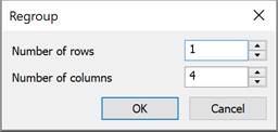


 – Disables display of borders of selected cells.
 – Display of outer borders of selected cells.
 – Display of all borders – internal and external.


 – Shrink horizontally;
 – Word wrap.
 – Shrink text height;
 – Expand row height;
 – Add virtual rows.


Using gestures to quickly call commands
Gestures are used to quickly call commands from the main menu of the table editor. Gestures are performed with the right mouse button pressed in the table editor field.
NOTE If a hint of the command to be executed appears when performing a gesture, you can lower the right mouse button.
Right – Calcilator
Left – Notebook
Up – Expression builder
Down – Cell properties

Right hook – Redo
Left hook – Undo

Closed area of selected cells clockwise – Group (cells to be grouped are pre-selected)
Closed area of selected cells counterclockwise – Ungroup
Symbol "z" on selected cells – Clear (cells to be cleared are pre-selected)
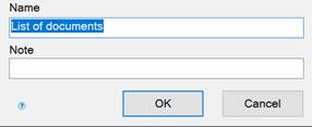
Saving a table template to the database
To save a table template, use the standard dialog for saving database objects.
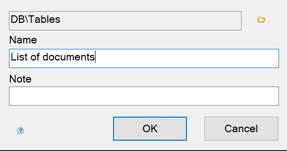
Parameters:
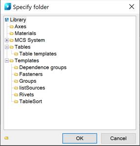
Path – select the path to the object in the database. To select the path, click the button with the folder image  . In the Specify folder dialog, select a folder in the database to save the object or create a new one.
Name – the object name.
Note – note to the object.
Selecting a table template from the database
The table template is selected using the database manager. To select a template, left-click on it in the preview window.
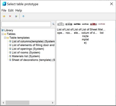
Options:
Toolbar – manages database objects.
Object tree – the database composition in form of a tree.
Search bar – search for objects through the object tree.
Preview window – preview and selection of objects.
Toolbar commands
Add folder – Adds a folder to the specified location in the object tree.
Delete – Deletes the selected object or folder.
Edit note – changes the name and note of the selected object.
Context menu commands
Import – Imports a database object.
Export – Exports a database object.
Send by email – exports an object and sends it to the specified email address.
Cut – Cuts an object, a folder.
Paste – Pastes a previously cut object, folder.
Paste shortcut – Pastes a shortcut to a previously cut object, folder.
Add folder – Adds a folder to the specified location in the object tree.
Delete – Deletes the selected object or folder.
Edit note – changes the name and note of the selected object.
Publish – makes the object visible to other users of the network database. Objects can be published by the administrators and the editor (own objects).
UnPublish – makes the object invisible to other users of the network database. The publication can be unpublished by administrators and the editor (own objects).