
 De
De  Es
Es  Fr
Fr  Pt
Pt 

-
-
-
-
-
-
-
-
-
-
-
-
-
-
-
-
-
-
-
-
-
-
-
-
-
-
-
-
-
-
-
-
-
-
-
-
-
-
-
-
-
-
-
-
-
-
-
-
-
-
IFC viewer
-
-
-
-
-
-
-
-
-
-
-
-
-
-
-
-
-
-
-
-
-
-
-
-
-
-
-
-
-
IFC viewer
 Functional panel:IFC.
File viewer IFC (Industry Foundation Classes). IFC is used as the format for the information model building BIM (Building Information Modeling).
Import models
-
Run the import command:
- Button
 "Import" in the main function bar menu "IFC".
 - Button "Import" in the tree.
-
 Command line: IFCVIEW3D.
- Button
-
Select the IFC file and confirm.
Begin analysis and file import nanoCAD environment. Download time depends on the capacity of the computer and the complexity of the file.
-
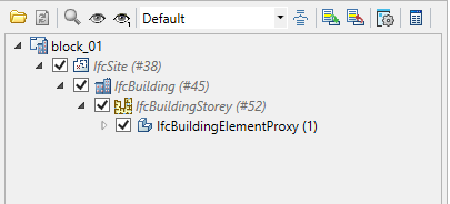
After importing the tree items will be available. When you import multiple serial models, the tree will be displayed several projects.
View models
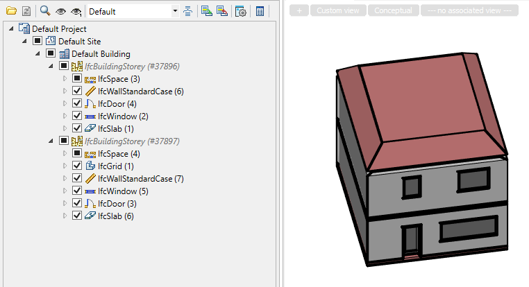
Viewing patterns by using wood elements.
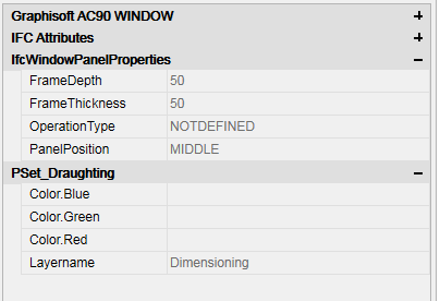
When selecting a tree node (object), its attributes are displayed on the "IFC properties" functional panel. Each object type has its own set of attributes.
Each type of object is located on its own layer and has its own color. Layer and color for objects is configured in the design settings.
The name of the objects is taken from the Name and LongName properties. If the object does not have the Name or LongName parameters, the name will be composed of IfcType and IfcId and displayed in gray italics.
Objects are controlled using menu commands.
The model is rotated using standard means nanoCAD.
| Example: |
IFC model transformation
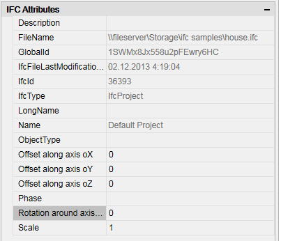
After importing the model, an additional special object "IFC Project" appears in the drawing to display the path to the IFC file, the properties of the root node of the project and the transformation of the model in the drawing using the "grips".

1.  Drag grip in XY plane.
2.  Scale selection grip.
3.  Rotary grip.
You can also transform the IFC model via the IFC properties panel. To do this, select the root node of the model in the "IFC" panel and switch to the "IFC properties" panel. This panel allows you to set the model offset along the oZ axis.
The parameters of the transformed model together with the configured visibility and color of the IFC objects can be imported using the  "Information model export" button, and then imported into another drawing using the
  "Information model import" button located on the "IFC" panel.
Main menu of the functional panel
Depending on the selected element in the tree, the following commands become available:
-
Import - opens a dialog for selecting a file to import.
-
 Delete - removes the selected element and all its descendants from the model.
 -
 Refresh IFC - updates the model tree.
 -
 Drop-down list for selecting a grouping.
 -
 Grouping - opens the "Grouping" dialog for setting up the grouping of objects in the tree of elements.
 -
Information model import - imports an object's information model (position, rotation, scale, visibility, colors, etc.) from a JSON file.
-
Information model export - exports the object's information model (position, rotation, scale, visibility, colors, etc.) to a JSON file.
-
 Show/Hide in model - controls the display of the selected element and all its descendants. You can also control the display using the switch to the left of the element's name.
 -
 Show/Hide only this - toggles the display between the selected element and elements of the same parent.
 -
 Show on drawing - focuses and selects an object in the drawing (in model space).
 -
 IFC import settings - opens the "IFC import settings" dialog.
 -
 IFC properties - opens the "IFC Properties" functional panel.
| Note: |
The commands of the context menu of the tree of elements duplicate the commands of the main menu of the functional panel. |
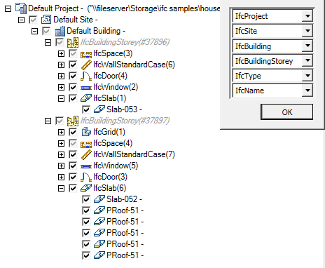
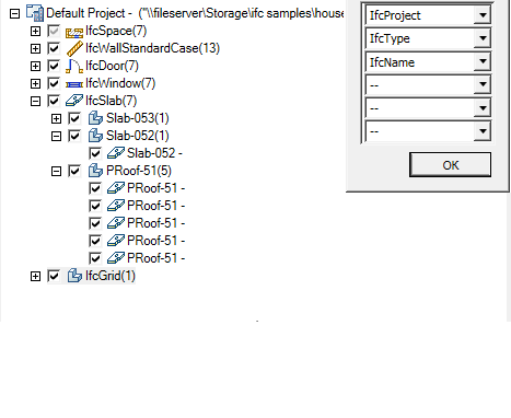
Grouping
By default, elements in the tree are grouped in the following sequence: Project - Plot - Building - Floor - Object type - Object.
It is possible to select another grouping method (from the grouping selection list) or assign a custom one.
Standard groupings: Default, Type, Floor, Layer.
To view the composition of a grouping, select the required grouping and click the "Grouping" button. In the "Grouping" dialog, the fields will display the parameters of the selected grouping. To create a custom grouping, change the composition of the fields and click the "OK" button.
| By default | Custom |
|---|---|
|
|
| Note: |
When creating a custom grouping, elements are additionally grouped by the title of the name. The title of the name is the text of the name from the first character to the first space (or end of line). |