De
De  Es
Es  Fr
Fr  Pt
Pt 

-
-
-
-
-
-
-
-
-
-
-
-
-
-
-
-
-
-
-
-
-
-
-
-
-
-
-
-
-
-
-
-
-
-
-
-
-
-
-
-
-
-
-
-
-
-
-
-
-
-
-
-
Hole group
-
-
-
-
-
-
-
-
-
-
-
-
-
-
-
-
-
-
-
-
-
-
-
-
-
-
Hole group
 Main menu: Construction - Utilities >
 Hole group.
Ribbon: Construction - Symbols >Hole group.
Toolbar: "Utilities") >Hole group.
 Command line: SPFILL.
Universal command for drawing holes. With its help, you can draw a new hole with centerlines, or by specifying a group of holes to assign them general properties with filling of a sector.
Procedure
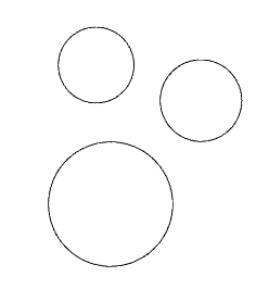
1. Draw holes from circles.
2. Call the command "Hole group".
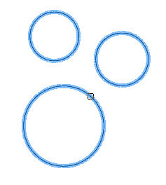
3. Select the required circles. Press the "Enter" key to complete the selection. The "Holes" dialog will open.
4. Adjust the hole settings and click "OK". The parameters will be applied to the holes. The holes will be created.

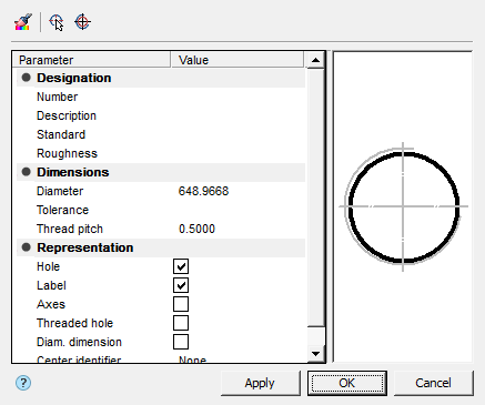
Dialog
The "Holes" editing dialog is opened by double-clicking. The dialog consists of: Toolbar, Parameter List, Graphics Window.
Toolbar
 Match properties - this command allows you to copy parameters from holes already installed in the drawing.
 Select holes - the command allows you to select additional holes from the drawing.
 Create holes - the command creates holes of the specified diameter. To dynamically set the radius on the screen, hold down the left mouse button and move the cursor.
Parameter List
Designation
- Number - specifies the number of the hole in the group.
- Description - specifies the hole table description field.
- Standard - sets the field to the standard of the hole table.
- Roughness - allows you to specify the roughness of the hole (displayed in the hole table).
Dimensions
- Diameter - hole diameter.
- Tolerance - the "..." button opens the "Tolerances" dialog, from which you can select a tolerance.
- Thread pitch - hole thread pitch.
Representation
- Hole - hole display switch.
- Label - label display switch.
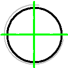
- Axes - axis display switch.
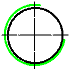
- Threaded hole - thread display switch.
- Diam. dimension - diametrical dimension display switch.
- Center identifier - drop-down list for selecting the hole center designation.
| Note: |
Also, the parameters of the "Representation" section can be configured through the graphics window. |
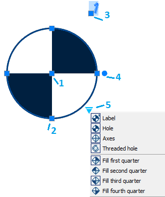
Graphics Window
The graphics window allows you to see the resulting hole representation and customize the representation by directly specifying elements.
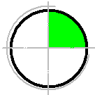
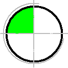
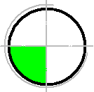
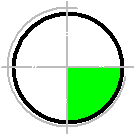
| Threaded hole | Axes | Fill first quarter |
|---|---|---|
|
|
|
| Fill second quarter | Fill third quarter | Fill fourth quarter |
|
|
|
Properties
The parameters on the "Properties" functional panel are similar to the parameters from the list of parameters of the "Holes" dialog.
Grips
1. Hole position change grip.
2. Diameter change grips.
3. Grip for changing the position of the hole number.
4. Hole rotation grip.
5. View adjustment grip.