De
De  Es
Es  Fr
Fr  Pt
Pt 

-
-
-
-
-
-
-
-
-
-
-
-
-
-
-
-
-
-
-
-
-
-
-
-
-
-
-
-
-
-
-
-
-
-
-
-
-
-
-
-
-
-
-
-
-
-
-
-
-
-
-
-
-
-
-
-
-
-
-
-
Hole chart
-
-
-
-
-
-
-
-
-
-
-
-
-
Hole chart
 Main menu: Mechanical - Symbols >
 Hole chart.
Ribbon: Mechanical - Symbols >Hole chart.
Toolbar: Hole chart (on toolbar " Symbols").
 Command line: MCHOLECHART.
The command is designed to create automatically updated statements for a group of holes.
Procedure
1. Call command "Hole chart".
2. Specify the insertion point of the coordinate system.
3. Set the angle of rotation of the coordinate system.
4. Specify the required holes and circles in the drawing, or create new ones using the "Create N" context menu command. To complete the selection (creation), press the "Enter" key. The "Hole chart" dialog opens.
5. In the "Hole chart" dialog, specify the name and type (dekatrov or polar) of the coordinate system, add (or delete), if necessary, holes.
6. Insert into the drawing the necessary tables: List of coordinates, Table of holes, Table of values.
7. Click "OK." Tables will be built. Holes will be associated with tables and coordinate system.
| Note: |
To see the holes in the drawing associated with this coordinate system, double-click on the anchor. |
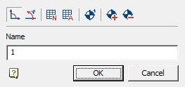
Edit dialog
The "Hole chart" dialog is called for editing by double-clicking on the coordinate system.
The "Hole chart" dialog contains:
-
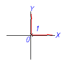
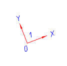
Graphic switch type coordinate system:
 Cartesian or
  Polar.
 -
Hole table creation buttons:
-
 List of coordinates - an automatically updated table is formed with the coordinates of each hole.
 -
 Hole table - a table is formed, grouped by hole diameter. Each group of identical holes is assigned a letter.
-
-
Button
 Number holes - the command automatically assigns consecutive numbers or letters to the holes (according to the setting for Hole Designation).
 -
Button
 Add holes - this command allows you to add holes to the report.
 -
Button
 Remove holes - this command allows you to remove holes from the report.
 -
Field "Name" - the name of the coordinate system. It is added to the hole designation as a prefix.
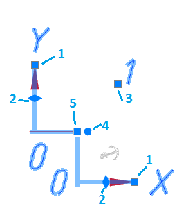
Grips
The handles of the report tables are similar to the handles of ordinary tables.
Coordinate system:
1. Axle Strength Handles.
2. Handles parallel transfer axes.
3. Handle move the designation of the coordinate system.
4. Handle rotation coordinate system.
5. Handle transfer coordinate system.