
 De
De  Es
Es  Fr
Fr  Pt
Pt 

-
-
-
-
-
-
-
-
-
-
-
-
-
-
-
-
-
-
-
-
-
-
-
-
-
-
-
-
-
-
-
-
-
-
-
-
-
-
-
-
-
-
-
-
-
-
-
-
-
-
-
-
-
-
-
-
-
-
Graphics
-
-
-
-
-
-
-
Graphics
The drawing should provide recognition of the parametric 2D view of the object from the database with maximum legibility and contain all required views for the element (including the graphic for which the preview was created).
The expressions "single parametric element from the database", "detail" and "GOST" (in lower case so that the letters are not confused with the standards) are set as equivalent.
The drawing of the detail or details should be created in one file. The file name should contain all the numbers of the standards used to create the detail and, if needed, the description. (for example, "GOST 7798-70 Hexagon Head Bolts Product Grade A").
General requirements
By default the scale is set 1:1. The scale to draw a graphic is selected by the user, but the drawing should be legible. It is recommended to draw a detail according to its values from the table.
All objects are drawn in the model space. Default settings are used to create elements.
Layers
By default the line width is set to default for all layers and objects.
Layers, used for the drawings:
|
Layers name |
Parameter - linetype of the object |
Colour |
Objects |
|
MAIN |
0 or not specified |
White |
Objects, which should have this linetype Insertion point |
|
THIN |
2 |
Red |
Objects, which should have this linetype Hatch |
|
DASHED |
4 |
Green |
Objects, which should have this linetype |
|
AXIS |
Specified by the command |
Red |
Objects, which should have this linetype |
|
WORKING |
Checkbox "working object" |
Yellow |
Objects, which should have this linetype |
|
DIMENSIONS |
Not specified |
Blue |
Dimensions and text formulas Names of GOSTs, implementations, views and other comments |
The "centre Line" parameter should be set for graphic objects after their replacement on the specified layer.
Placement of graphic
The separate details and the separate implementations of one GOST should be separated from the other GOSTs and implementations in the drawing (zonally or with the rectangular frames). If there is more than one GOST or implementation, the GOST number or implementation name should be written above of the group of implementation or GOST views.
The views should be in the projective connection in the drawing.
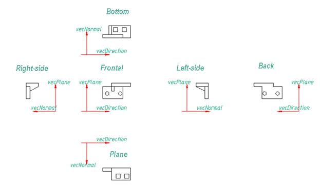
Figure 1. Placement Drawing Views.
The views, which are out of the projective connection, should have clear names to define the relation.
It is recommended to group the views with cuts, simplified views and views with dimensions near their projective views.
If one or several views belong to one GOST/implementation, they should have clear names to define the relation (for example: "Left-side view (all implementation)", "Frontal (GOST 7798,7805, 7806)"). The graphic of the details view should have a name.
The detail should be oriented that the detail's direction (vecDirection of script) should coincide with the OX axis (to the right for the frontal view).
Dimensions
To set the dimension, take into account:
- Correct recognition;
- Legibility of the drawings;
- Unified system for design documentation requirements.
It is not permitted to place the dimensions inside the hatched area (the hatch is not allowed to flow over the dimension values).
Hatch
Hatch should be executed by the "User defined" type, slope angle 45 degrees. A hatch step should be specified parametrically according to the width of the narrowest hatched part (s):
For example:
1. For thin-wall objects: s/2;
2. For massive objects: s/8;
3. Intermediate step: s/4.
A hatch type can be specified in absolute units divisible by 10 (0.1;1;10;100)
You can ignore these rules if you need to hatch in both sides.
Parameters
Using the "Set parameter" tool, set the parameter for the dimensions. It is possible to switch off the "Work object" checkbox for the dimensional view only.
It is recommended to avoid text formulas in the drawing fields (place the calculations in the script).
Text formulas are allowed to be placed in the drawing, if you need to calculate the parameters of the implementation's view and it is defined that their use is not needed in the script.
Use of non-English letters is only allowed in the names
When specifying the parameter's name take into account:
- Similar names existing in the database
- Parameters names in the GOST
- Meaningful parameters names, corresponding to the syntax of the C language.
If possible, avoid difficult arithmetic expressions set in the dimension parameters (it is recommended to use the Protected variables).
Other requirements
The views names should be specified with text of 10mm height. Text formulas should have the text height of 5 mm. The views names are placed above the view, text formulas are placed below the view.
Specify meaningful names for the blocks in the array in English (for example, hole, chamfer etc.). The insertion point of the blocks, used for creating an axial array, should be placed in the centre of the axial array.
It is possible to add an image of the detail, copied from the GOST, into the drawing field, if it does not cause difficulties in legibility and overlap other objects.