
 De
De  Es
Es  Fr
Fr  Pt
Pt 

-
-
-
-
-
-
-
-
-
-
-
-
-
-
-
-
-
-
-
-
-
-
-
-
-
-
-
-
-
-
-
-
-
-
-
-
-
-
-
-
-
-
-
-
-
-
-
Geocalculator
-
Geocalculator
 Ribbon: Topoplan – Settings >
  Geocalculator
Menu: Topoplan – Settings >  Geocalculator
Toolbar: Topoplan Settings >  Geocalculator
 Command line: NG_GEOCALC
The command allows you to:
Calculate the parameters of transformation of coordinate systems
spatial 3-dimensional:
· 7 parametric Helmert transformation;
· 9 parametric Helmert transformation;
· Molodensky transformation.
flat rectangular:
· 4 parametric Helmert transformation;
· 5 parametric Helmert transformation.
Recalculation of coordinates
geodetic:
· geographic to flat rectangular Gauss-Kruger or UTM and back;
· geographic and rectangular between 3-dimensional coordinate systems, using the recalculation parameters;
flat arbitrary:
flat rectangular between 2-dimensional coordinate systems, using the recalculation parameters.
Calculations are made both for individual points and for files.
Calculating distances and directions on a plane and an ellipsoid
The source data is located in the LIB directory in the program installation directory (Nanosoft AS\nanoCAD x64 26.0\UserDataCache\maplib\LIB). Changing the directory name and its location is not allowed.
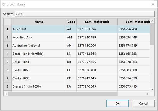
The Ellipsoid Library is required for the command to work. The ellipsoid data is a text file gt_ellips.csv, containing the name, code, major and minor semi-axes in meters, and the denominator of compression for each ellipsoid. The field values are separated by commas.
A fragment of the file is given below:
NAME,CODE,A,B,RF
Airy 1830 ,AA,6377563.396,6356256.9090,299.324964600
Modified Airy ,AM,6377340.189,6356034.4480,299.324964600
Australian National ,AN,6378160.000,6356774.7190,298.250000000
The file can be edited by the user, but the file name and format should not be changed. Viewing the ellipsoid library is available from the  Calculate Transformation Parameters dialog.
The  button opens the ellipsoids librry.
The main window is the transaction log window. All calculation results are displayed in the log window.
The geocalculator has a built-in toolbar, which is located under the window title.
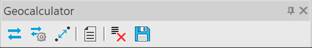
 - Transformations
 - Transformation parameters
 - Distances and directions
 - Templates
 - Clear log
 - Save log
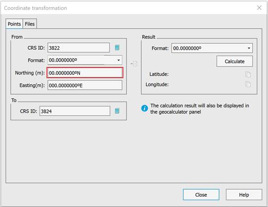
Transformations
The coordinates are recalculated using EPSG codes in a dialog box opened from the Transformations toolbar.
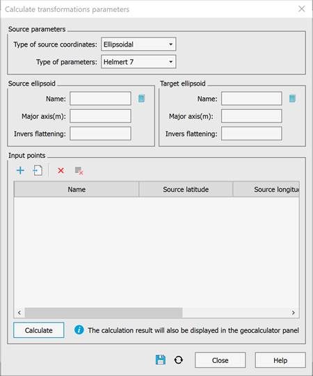
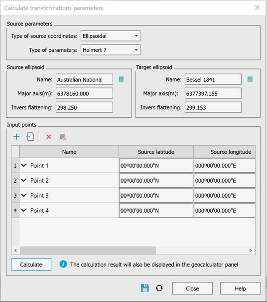
Transformation parameters
The coordinates are recalculated in the dialog box opened from the Transformation Parameters toolbar.
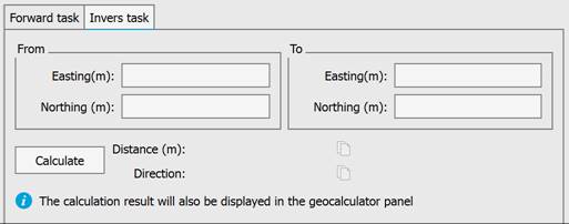
Distances and directions
Distances and directions are recalculated in the dialog box opened from the  Distances and directions toolbar.
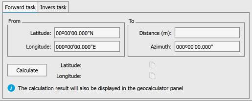
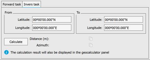
After selecting an ellipsoid from the library, the following tasks can be solved:
Azimuth and distance applied to a geodetic line.
Forward geodetic task.
Inverse geodetic task.
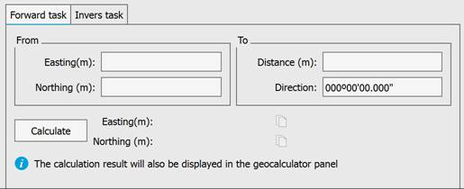
On a plane.
Forward and inverse geodetic tasks.
Templates
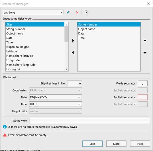
Skip – The field in the string is ignored.
Latitude – Latitude.
Hemisphere latitude – Latitude hemisphere – northern or southern.
Longitude – Longitude.
Hemisphere longitude – Longitude hemisphere – eastern or western.
Easting GK – Direction to the east (horizontal). Gauss-Krüger projection, in meters.
Northing GK – Direction to the north (vertical). Gauss-Krüger projection, in meters.
Easting UTM – Direction to the east (horizontal). Universal Transverse Mercator projection, in meters.
Northing UTM – Direction to the north (vertical). Universal Transverse Mercator projection, in meters.
Easting target EPSG – Output easting coordinate for EPSG transformation.
Northing target EPSG – Output northing coordinate for EPSG transformation.
Ellipsoidal height – Ellipsoidal height, in meters.
Object name – object name.
String number – string number.
Date – Date.
Time – Time.
Target latitude – Latitude. Geographic coordinates of the target (calculated) coordinate system.
Target longitude – Longitude. Geographic coordinates of the target (calculated) coordinate system.
Hemisphere latitude target – Latitude hemisphere (north/south) of the target coordinate system.
Hemisphere longitude target – Longitude hemisphere of the target coordinate system.
Northing source – Northing direction (vertical) of the source coordinate system.
Easting source – Easting direction (horizontal) of the source coordinate system.
Northing target – Northing direction (vertical) of the target coordinate system.
Easting target – Easting direction (horizontal) of the target coordinate system.
Source latitude – Latitude. The geographic coordinates of the source (initial) coordinate system.
Source longitude – Longitude. The geographic coordinates of the source (initial) coordinate system.
Hemisphere latitude source – Hemisphere source latitude.
Hemisphere longitude source – Hemisphere source longitude.