De
De  Es
Es  Fr
Fr  Pt
Pt 

-
-
-
-
-
-
-
-
-
-
-
-
-
-
-
-
-
-
-
-
-
-
-
-
-
-
-
-
-
-
-
-
-
-
-
-
-
-
-
-
-
-
-
-
-
-
-
-
-
-
-
-
-
-
-
-
-
-
-
-
-
Fixed joint
-
-
-
-
-
-
-
-
-
-
-
-
-
-
-
-
-
-
-
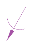
Fixed joint
 Main menu: Construction - Weld >
 Fixed joint.
Ribbon: Construction - Symbols >Fixed joint.
Toolbar: "Weld">Fixed joint .
 Command line: SPFIX.
Procedure
1. Call the command "Fixed joint".
2. Indicate the place of the fixed joint.
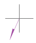
3. Pick a break point.
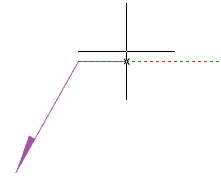
4. Specify the end point of the leader or press the "Enter" key, then the end point of the leader will be the break point. The "Joints" editing dialog will open.
5. Set the type of joint in the "Joints" editing dialog and confirm the setting with the "OK" button.
6. The Fixed joint will be built.
Dialog
| Important! |
When you select the fixed joint "Soldired Joint Leg" or "Weld point", you cannot call the dialog from the object for editing. |
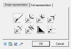
The editing dialog contains additional commands and two tabs: "Simple representation" and "Full representation".
-
 Place spot welds - the command is intended for insertion of weld point elevations in the drawing.
 -
 Along closed contour - the command is intended to add the symbol "Joint along closed contour" to the connection designation.
 -
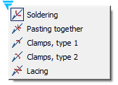
The "Simple representation" tab allows you to select the type of fixed joint.
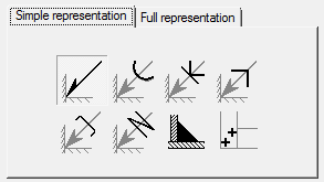
The following designations for fixed joints are available:
Seam denotation Soldering Pasting together Clamps, type 1 


Clamps, type 2 Lacing Soldired Joint Leg Weld point 


Depending on the selected type, the "Full representation" tab will be available.
-
The "Full representation" tab allows you to customize the fixed joint symbol.
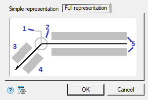
Input fields and graphic elements are edited on the tab. To edit input fields and turn on / off graphic elements, click LMB on them. When editing input fields, dialogs for editing fields appear, containing an input field and additional commands.
1. Graphic element "Field joint".

2. Graphic element "Joint along closed contour".

3. Number designation input field.
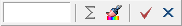
The editing dialog contains:
-
Value input field.
-
Command
 "Sum" - the number of welded seams with the same number is counted. Deleting or changing a seam number designation is automatically displayed in the full designation for that joint number.
 -
Command
 "Copy properties" - allows you to copy properties from an existing dimension in the drawing.
 -
Command
 "OK" - closes the dialog, saving changes.
 -
Command
 "Cancel" - closes the dialog without saving changes.
4. Input field for the designation of the control complex or the seam control category.

The editing dialog contains:
-
Value input field.
-
Command
"Copy properties" - allows you to copy properties from an existing dimension in the drawing. -
Command
"OK" - closes the dialog, saving changes. -
Command
"Cancel" - closes the dialog without saving changes.
5. Input fields for the symbol.

The editing dialog contains:
-
Value input field.
-
Buttons for quick insertion of special symbols for fixed joint:
 - Soldered leg;
 - Remove weld reinforcement;
 - Treat seam overflows and unevenness with graded junction to parent metal;
 - Discrete double unfaced seam;
 - Discrete double faced seam;
 - Opened contour seam.
 -
Command
"Copy properties" - allows you to copy properties from an existing dimension in the drawing. -
Command
"OK" - closes the dialog, saving changes. -
Command
"Cancel" - closes the dialog without saving changes.
-
Properties
Seam denotation:
- Text above self of leader
- Text under self of leader
- Text above leader
- Text under leader
- Enable calculate joints
- Count of joints
- Field joint
- Joint along closed contour
Soldering, Lacing, Clamps type 1, Clamps type 1, Pasting together:
- Joint along closed contour
- TR item number
Grips
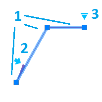
Seam denotation:
1. Move grips - Move the endpoints of the parts of the weld symbol.
2. "Mirror arrow side" grip - changes the side of the arrow.
3. "Weld seam properties" grip - opens a list of available graphic elements. In the list, you can enable or disable the display.
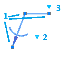
Soldering, Lacing, Clamps type 1, Clamps type 1, Pasting together:
1. Move grips - Move the endpoints of the parts of the weld symbol.
2. Joint type selection grip - opens a drop-down list for selecting a joint type.
3. "Weld seam properties" grip - opens a list of available graphic elements. In the list, you can enable or disable the display.
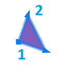
Soldered Joint Leg:
1. Move grip - allows you to move the leg.
2. Grips "Change leg size" - allow you to change the size of the leg.
Weld point:
1. Move grip - Allows you to move the weld point in the drawing.