De
De  Es
Es  Fr
Fr  Pt
Pt 

-
-
-
-
-
-
-
-
-
-
-
-
-
-
-
-
-
-
-
-
-
-
-
-
-
-
-
-
-
-
-
-
-
-
-
-
-
-
-
-
-
-
-
-
-
-
-
-
-
-
-
-
-
-
-
-
-
-
-
-
Feature control frame
-
-
-
-
-
-
-
-
-
-
-
-
-
-
-
Feature control frame
 Main menu: Mechanical - Symbols >
 Feature control frame.
Ribbon: Mechanical - Symbols >Feature control frame.
Toolbar: Feature control frame (toolbar " Symbols").
 Command line: MCTOL.
The tolerance can be set depending on the quality of the specified size.
Procedure
1. Call command.
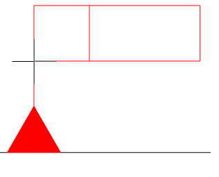
2. Pick a point on the object. When you select a base surface, the graphic element is highlighted in green.

3. Point to the next point to pin the line of the mark. The sign line is drawn along the normal to the specified surface.
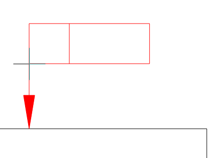
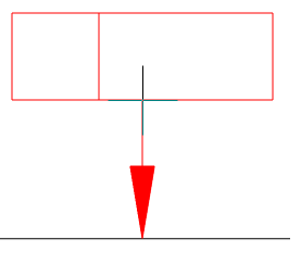
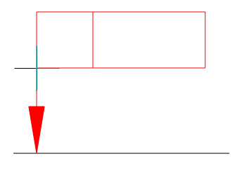
The sign line may extend from the corner of the frame or from the middle of its side. To control the display of these elements, you must call the context menu and select "Sides" or "Angles".
| Sides | Angles |
|---|---|
|
|
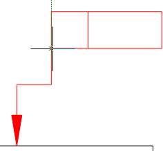
When you select the "Base" line in the context menu, a triangle symbol is drawn on the leader.
When you select the "Tolerance" line in the context menu, an arrow is drawn on the callout.
| Base | Tolerance |
|---|---|
|
|
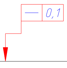
4. Next, place a tolerance mark in the place you need. To do this, using the mouse cursor, specify new points in the drawing. To undo the last action, use the "Back" command from the context menu. To finish, press the "Enter" key, a dialog box will appear "Form&plane position tolerance".
5. In the "Form&plane position tolerance" dialog box, enter the required parameters and click the "OK" button.
6. The tolerance of the form and plane will be built.
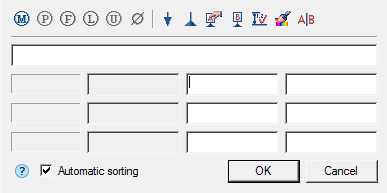
Dialog edit
The editing dialog consists of a toolbar and a workspace.
Workspace
The working area of the dialog box is a list of 4 lines, allowing add header and form 3 rows of values in the tolerance.
Lines are divided into 4 columns:
-
Type of tolerance column
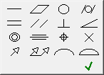
The field of this column allows you to add a type of tolerance. In each field, you can enter 2 types of tolerance by selecting the left or right button of the field.
When you click on the buttons, a form for selecting the type of tolerance appears.
-
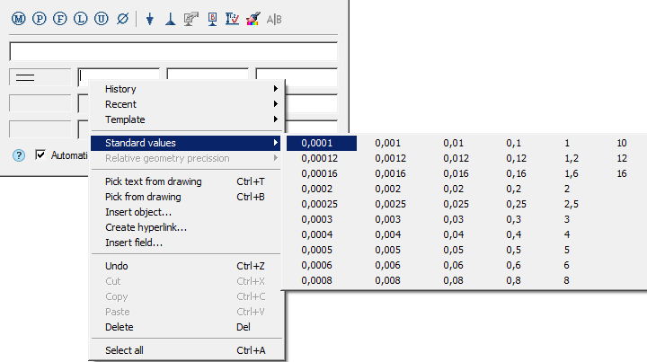
Column of tolerance deviation
The tolerance deviation value is entered in the fields of this column. The tolerance deviation value can be taken from the "Standard values" when the context menu is opened in the input field.
-
Base designation column
In the fields of this column, the notation for bases is entered.
-
Column notes
Notes are entered in the fields in this column.
Dialog Toolbar
 Dependent tolerance - the command inserts the designation "Dependent tolerance" in the columns "tolerance deviation values" and "bases designation".
 Extended tolerance range - the command inserts the symbol "Extended tolerance range" in the column "tolerance deviation values".
 Extended tolerance range - the command inserts the symbol "Non-rigid part" in the column "tolerance deviation values".
 Extended tolerance range - the command inserts the symbol "Least material requirement" in the column "tolerance deviation values".
 Extended tolerance range - the command inserts the symbol "Unequally-disposed modifier" in the column "tolerance deviation values".
 Diameter - the command inserts the designation "Diameter" in the column "tolerance deviation values".
 Set additional leader - the command allows you to set an additional leader for an editable tolerance.
 Set additional base - the command allows you to set an additional base for an editable tolerance.
To install additional callouts, you must:
- Call command;
- Select object;
- Bring the callout line to the tolerance mark.
 Specify base - the command allows you to specify the base, to do this, call the command and point to the previously placed base symbol on the drawing. The letter designation of the base will be automatically applied in the current input field. When linking the base designation in the drawing, the cursor must be in the base designation input field.
 Insert base denotation - allows you to insert a base symbol when it is missing in the drawing.
 Linked to dimensions - the command serves to fill the deviation value depending on the quality of the specified size.
To fill the value of the deviation is necessary:
-
Select the type of deviation.
-
Call command "Linked to dimensions".
-
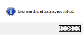
Indicate the size with the assigned quality. A link will be created, otherwise, if the qualification is not affixed, a corresponding message will be displayed.
-
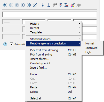
From the context menu of the deviation value input field, select "Relative geometry precission".
"Relative geometry precission" has 3 degrees: Normal, Increased and High.
Note: If a mark for the shape deviation mark has been applied to the size with the specified quality, the context menu bar of the tolerance value "Relative geometry precission" will be active.
The relationship with the size is NOT associative: the tolerance field established relative to the size will NOT change along with the size value. Moreover, all information about the connection is lost after closing the edit edit form admission dialog.
Thus, if it is necessary to select the value for admission again, the connection will have to be imposed again.
 Match properties - this command allows you to copy values from the tolerance already entered.
 Insert separator - the command inserts a separator into the database designation field.
Switch Automatic sorting - manages automatic database sorting. When you turn on the designation of bases are put alphabetically, taking into account the previously used letter designations of species, sections, sections.
| Note: |
Deleting symbols of basic surfaces or drawing additional designations of types, sections, sections will lead to automatic re-sorting of all associated text symbols, including references to them in the technical requirements. |
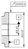
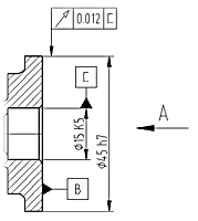
Put down two designations of the basic elements: "A", "B". Added view "A" to drawing. The designation of bases was adjusted automatically.
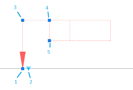
Grips
1. Grip moving arrows.
2. Arrow type grip.
3. Grip move the nodes of the arrow (maybe several).
4. Grip joining the sign. Allows you to change the point of attachment of the leader line to the sign both in the corners and along the sides.
5. Sign move grip.