-
-
-
-
-
-
-
-
-
Export
-
-
-
-
-
-
-
-
-
-
-
-
-
-
-
-
-
-
-
-
-
-
-
-
-
-
-
-
-
-
-
-
-
-
-
-
-
-
-
-
-
-
-
-
-
Export
 nanoCAD button -
  Export
 Ribbon: Output –Export >
 Export
 Menu: File –
  Export…
 Command line: EXPORT, EXP
A nanoCAD document data can be exported to:
· document format AutoCAD (*.dwg);
· file format for exchange of graphical information (*.dxf);
· 3D PDF (*.pdf) format to visualize 3D models in Acrobat Reader;
· DWF (*.dwf, *.dwfx) format for exchange of large volumes of data of 2D and 3D design, reading, printing and reviewing;
· STL (*.stl) layout format used for stereolithography. STL files are used in additive manufacturing to create 3D prototypes from 3D CAD models. Export options available for STL.
NOTE The 3D PDF export command is intended for 3D content only. To save data in regular PDF format, use Document plot and select a PDF plotter, such as the Internal PDF Plotter.
In case 3D Module is available, the following 3D are also available for export:
|
Format |
Version |
Description |
|
Parasolid (*.x_t; *.x_b) |
10.0 |
Text and binary file formats of Parasolid geometric kernel. They are used by such CAD-systems as NX, Solid Edge, SolidWorks. |
|
IGES (*.igs; *.iges) |
5.3 |
Digital Representation for Communication of Product Definition Data — 2D/3D vector graphics format; is used to transfer 2D and 3D data of drawings between dissimilar CAD systems. |
|
STEP (*.step; *.stp) |
203, 214 |
Standard for Exchange of Product model data — a set of ISO 10303 standards used in CAD, which allows describing the entire lifecycle of a product, including manufacturing technology and products quality control. It is gradually replacing IGES standard due to its wider information storage capabilities. |
|
ACIS (*.sat) |
2.0 |
Format to exchange data between 3D modeling systems using ACIS core. |
|
VRML (*.wrl) |
2.0 |
File format for describing interactive 3D objects and virtual worlds. VRML is designed for use in Internet and is the standard of 3D graphics in the Network. |
|
JT (*.jt) |
- |
An open format for describing 3D data used for visualization, shared work and data exchange in CAD. |
|
COLLADA (*.dae) |
|
A universal 3D format that supports any type of data (splines, geometry, light, materials, animation, etc.). |
|
C3D (*.c3d) |
|
An extended storage format for the geometric model that supports reading individual model objects from a file in an arbitrary order and allows you to obtain information about the model structure and its objects without loading the entire model from the file. |
|
glTF (*.gltf; *.glb) |
- |
An open file format for 3D scenes and models, developed and supported by the Khronos Group. It has the following main advantages: small file sizes, fast loading and processing, full representation of the 3D scene. gltf format stores data mainly in JSON format, glb is the binary form of glTF. |
You can export both the entire document content or only selected data.
Unlike the Save as command, the Export command allows you to save the edited document with a new name without closing it.
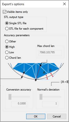
For STL and JT formats the Settings… button is available, which opens the Export’s options dialog box:

Options:
Visible items only – enables/disables the export mode of only the active model and construction geometry that are displayed in the part or assembly. Only working solids are exported. Simplified solids contained in the assembly are not exported.
STL output type
Single STL file – creates a single STL document containing the components of the assembly. This option is not available in documents of parts.
STL file for each component – creates separate STL documents for each component of the assembly. Only working solids are exported; construction solids and simplified data are not exported.
Accuracy parameters

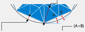
Conversion accuracy – the maximum allowable deviation in deflection (the distance between the converted surface and the triangle mesh). The range of values is determined by the dimensions of the exported model and is set in drawing units. The lower the value, the more accurate and smooth the model is and the larger the file size.
Normal’s deviation – the maximum allowable deviation in the angle of normals (the upper limit of non-parallelism of normals to the surface at any two points under the surface). The angle of deviation of the normal is set in the range from 1 to 60 degrees. The lower the value, the greater the accuracy of the model.
Max chord len – the maximum allowable distance between adjacent points (side of a triangle). The range of values is determined by the dimensions of the exported model and is set in drawing units. The lower the value, the greater the accuracy of the model.
The following options for setting accuracy parameters are available:
· Other – manual specification of the Conversion accuracy and/or Normal’s deviation parameters (entered in the field or set using the slider).
· High – selection of high model accuracy, normal deviation of 1 degree is automatically set.
· Low – selection of low model accuracy, normal deviation of 60 degrees is automatically set.
· Chord len – specification of the Max chord len parameter (entering the distance in the field).
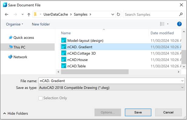
After running the command, in the opened Save Document File dialog:

1. Specify the path for the exported file in the Folder drop-down list.
2. Type a name in the File name field.
3. Select a format in the File type field.
4. Select the Save button.
In the nanoCAD list of dialog left part, only those user folders are displayed, the path to which is specified in the Common files location subsection of the Standard directories section of the Options dialog:
The Quick access list on the left side of the dialog displays the Explorer’s quick access folders. You can add a folder by selecting the Pin to Quick Access command in the folder’s context menu or by dragging the folder to the list. You can remove a folder from the list by selecting the Unpin from Quick Access command in the folder’s context menu.
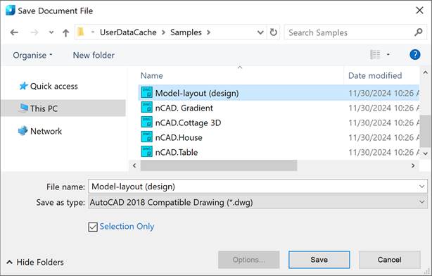
The export procedure for selected data is the same as the export procedure for all the data, except that the Selection Only checkbox is selected in the Save Document File dialog box:

attention! If no objects were selected before saving, the Selection Only checkbox is unavailable.


 De
De  Es
Es  Fr
Fr  Pt
Pt 
