

 De
De  Es
Es  Fr
Fr  Pt
Pt 

-
-
-
-
-
-
-
-
-
-
-
-
-
-
-
-
-
-
-
-
-
-
-
-
-
-
-
-
-
-
-
-
-
-
-
-
Exploding a Cloud into Points
-
-
-
-
-
-
-
-
-
-
-
-
-
-
-
-
-
Exploding a Cloud into Points
 Ribbon: Topoplan – Create TIN >
  Explode the Cloud into Points
Menu: Topoplan – Create TIN >  Explode the Cloud into Points
Toolbar: Create TIN > Explode the Cloud into Points
 Command line: NG_EXPLODE_POINTCLOUD
The command allows you to create Points or Geopoints or Blocks objects based on the cloud points for further creation of TIN surface by them (for example, by the Create TIN by Points)command.
Before using the Explode the Cloud into Points command, run the Drawing Units command. In the Insertion scale section, set the value in meters.
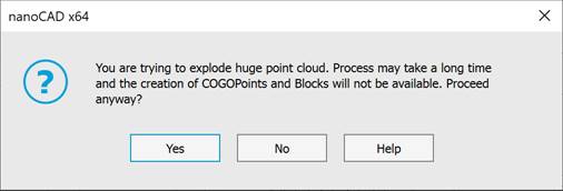
If the number of points in the cloud is more than 100000, COGOPoints and Blocks will be unavailable, and a warning will appear.
The command options are set in the Properties toolbar.
Options:
|
Result type |
Objects to be created based on the cloud points: Points, COGOPoints, Blocks. If the number of points in the cloud is more than 100000, COGOPoints and Blocks will be unavailable |
|
Delete source |
If Yes is selected – the source point cloud will be deleted after the split is completed. No – the source point cloud remains in the drawing. |
|
Use class |
If the cloud has been previously classified, it is possible to get only points of the specified class after splitting. |
Command prompts:
|
Apply changes? <Yes> or [Yes/No]: |
Yes – split into points will be made with the current settings. No – if the settings have been changed, they are not saved. Split into points will be made with the settings displayed immediately after starting the command. |
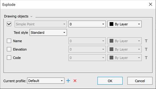
Then the Explode dialog box appears.
If a Geopoint object is selected, the layers will be locked.
Options:
|
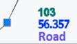
Drawing objects |
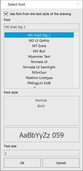
The section defines what components will be displayed for points on the screen: Marker, Name, Elevation (Z-coordinate), Code (point description). Each component can be assigned its own layer, color, and signatures - a font. The Select font dialog allows you to change the name, style and height. Or use a font from the drawing text style.
You can also specify the text style for the Marker.
|
|
|
|
|
Current profile |
Allows you to save all the settings made in the dialog to a profile for later use.
|
When you select “from Cloud” color, the points take on the color of the cloud (the current cloud display mode).
When splitting, a group with a name corresponding to the name of the cloud is created.
|
|
Note |
|
If a cloud being broken has more than 100000 points, the process may take a long time. |
