
 De
De  Es
Es  Fr
Fr  Pt
Pt 

-
-
-
-
-
-
-
-
-
-
-
-
-
-
-
-
-
-
-
-
-
-
-
-
-
-
-
-
-
-
-
-
-
-
-
-
-
-
-
-
-
-
-
-
-
-
-
-
-
-
-
-
-
-
-
-
-
-
-
-
-
-
-
-
-
-
-
Example of design drawings of extended objects
-
-
-
-
-
-
-
-
-
-
-
-
Example of design drawings of extended objects
It is especially convenient to use sheet space when drawing extended objects.
In the model space, a one-to-one (in real units) projection is drawn with an overall horizontal dimension of 500 mm.
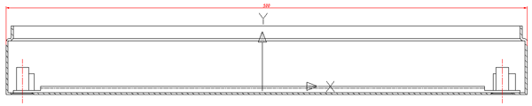
Task: to design this projection in sheet space on an A3 frame.
Result projection design in paper space.
Design
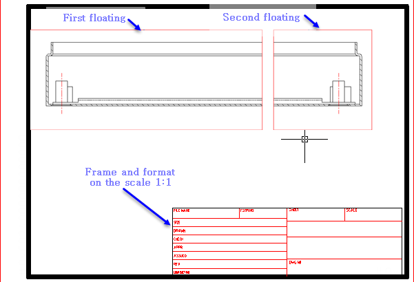
1. Let's move to paper space.
2. Insert an A3 frame by calling the "Format" command in the main toolbar nanoCAD Construction . After placing the frame in the paper space, a floating rectangular viewport is created by default. All objects located in the model space are displayed inside it. The image scale is arbitrary and requires editing later.
3. Let's change the size of the floating screen. To do this, click on its outline with LMB and move the highlighted corner points. Part of the projection will then be hidden by the outline of the viewport. We have made a kind of cropping of the image. You can also delete the existing viewport and add a new one of the required size.
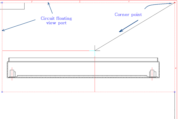
Move the corner points of the floating viewport
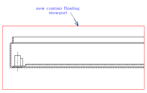
Result after the transfer of the image projection of the angular points of the contour floating viewport.
4. After the boundaries of the first viewport are defined, we set the image scale.
5. To obtain an image of the right part of the projection, we will make a copy of the floating screen and move it to the right.
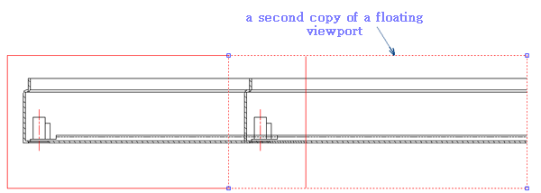
Move the screenshot to the right.
6. Using panning, we will set the view of the right part of the projection inside the right floating viewport. To do this, double-click LMB inside the viewport outline.
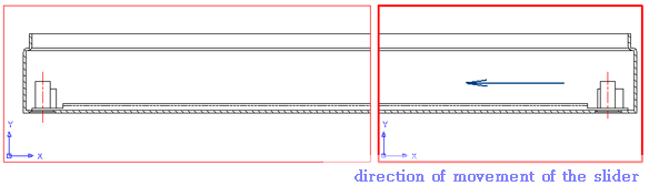
Changed the boundary of the right floating viewport.
Features when printing
Before printing the frame with projections, you need to move from the floating viewport area to the paper space area. To do this, double-click the left mouse button outside the viewport border. The paper space sign will appear.