
 De
De  Es
Es  Fr
Fr  Pt
Pt 

-
-
-
-
-
-
-
-
-
-
-
-
-
-
-
-
-
-
-
-
-
-
-
-
-
-
-
-
-
-
-
-
-
-
-
-
-
-
-
-
-
-
-
-
-
-
-
-
-
-
-
-
-
-
-
-
-
-
-
-
-
-
-
-
Elevation mark
-
-
-
-
-
-
-
-
-
-
-
-
-
-
-
-
Elevation mark
 Main menu: Construction - Level marks >
 Elevation mark.
Ribbon: Construction - Symbols >Level mark.
Toolbar: Level marks >Elevation mark.
 Command line: SPLEVEL.
Procedure
1. Call the command "Elevation mark".
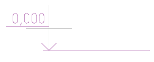
2. Pick an insertion point for the base elevation mark.
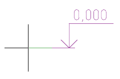
3. Select the position of the elevation mark text. The "Elevation mark" dialog will open.
4. In the "Elevation mark" dialog box enter the required values.
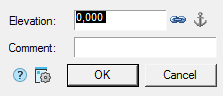
5. Click the "OK" button.
6. Specify the insertion points and text position for subsequent elevation marks. Subsequent elevation marks are associated with the baseline and their value is calculated automatically.
7. Press the "Enter" key or RMB to complete the construction of elevation marks.
Dialog
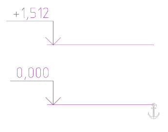
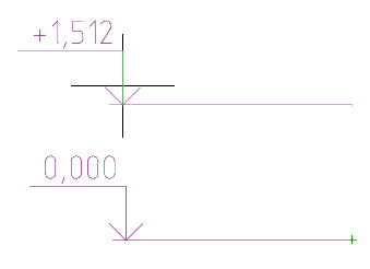
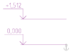
The "Elevation" text box contains the numerical value of the level in meters. The default value that appears in the window is automatically calculated and is the Y-axis distance from the insertion point of the base elevation to the specified elevation point (for the base elevation, the default is 0). Marks above zero are displayed with a "+" prefix, and below zero with a "-" prefix. The 0.000 mark has no prefix.
In the "Comment" column, you can enter explanatory text for the mark.
The  "Associative" button controls the association of the elevation mark with the base elevation. When editing associative elevations in the dialog box, the height value field is grayed out and the "Associative" button is shown when pressed.
To turn off the associativity of the editable mark, turn off the "Associative" button. If necessary, set associativity with a different elevation, click the "Associative" button and select the desired elevation in the drawing as the base.
If, after inserting, you call the base mark for editing, the  "Detach owned markers" (anchor) button will be highlighted in the dialog box. When you click on it, the base elevation mode is disabled and all associated elevations lose associativity. A level elevation automatically becomes base if one or more other elevations are associated with it.
Anchor
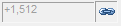
The "Anchor" object points to a base elevation mark to which other elevation marks are associated.
The number of associated level marks is indicated next to the anchor.
The display of associativity links is turned on / off by calling the "Edit" command: in the tooltip, in the context menu, RMB on the anchor.
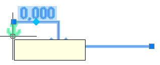
Grips
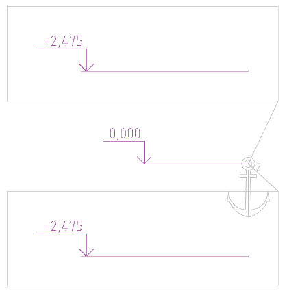
Elevation mark grips
1. Grip for moving the base.
2. Grip for adding new level marks. Pressing the knob activates the command for adding new level marks. The new level marks will be associated with the edited level mark, which in turn will become the base mark.
3. Grip for moving the position of the arrow.
4. Grip for specifying the base mark. When you press the grip, you must select the level mark that is the base for the edited level mark.
5. Grip for moving the level mark shelf along the Y axis.
The base elevation in the drawing is highlighted with an "Anchor" icon. When you hover over the "Anchor", a tooltip appears with a link to edit. When you select the "Edit" command for the "Anchor" icon, the elevation marks associated with the selected base elevation mark are highlighted in the drawing. To turn off the highlight, re-invoke the "Edit" command for the "Anchor" icon.
| Note: |
Hints are included in "Construction - Settings... - Tab "Main options" - Notifications - Enable Hints" |
Elevation mark anchor grips
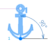
1. A grip for changing the calculated angle (by default, the coefficient of distance between marks is sin (90) = 1). The grip is used when calculations need to be performed not in the XY plane, but in some other custom coordinate system.
| sin(90) | sin(30) |
|---|---|
|
|
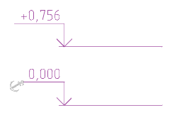
Linked elevation mark grips
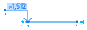
1. Grip for aligning to baselines. X-aligns the insertion point of the level mark with the insertion point of the base level mark.
2. Grip for moving the base.
3. Grip for moving the position of the arrow.
4. Arrow alignment grip. Aligns the X axis of the insertion point of the level mark arrow with the insertion point of the base level mark arrow.
5. Grip for moving the level mark shelf along the Y axis.