-
-
-
-
-
-
-
-
-
-
-
-
-
-
Dynamic Input
-
-
-
-
-
-
-
-
-
-
-
-
-
-
-
-
-
-
-
-
-
-
-
-
-
-
-
-
-
-
-
-
-
-
-
-
Dynamic Input
 Status bar: Button
 Hot key: F12
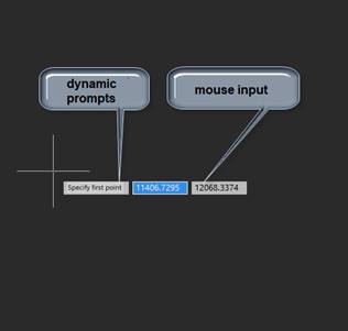
Dynamic input displays the command interface near the cursor in the drawing area. At the right time, current prompts, command requests, input fields, lists of selectable keywords, dimensions of edited geometry are displayed next to the cursor.
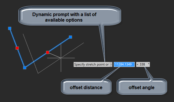
Dynamic input consists of three functional parts:
· Pointer Input;
· Dimension Input;
· Dynamic Prompts.
|
|
|
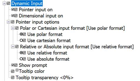
You can adjust them or switch them off in the Dynamic Input section of the Options dialog.
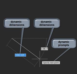
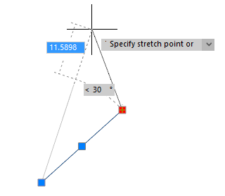
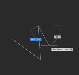
Dynamic dimensions are displayed when creating and editing lines, arcs and circles. The values of dynamically displayed dimensions can be edited, which makes it more convenient to draw and edit, when the exact distances, dimensions and angles of segments are known.
When constructing a linear segment, an arc segment or a circle, their linear and angular dimensions are displayed on the screen relative to the previous point. Dimensions are displayed with a thin dashed line. With the moving of cursor in the drawing, the values of dynamically displayed dimensions continuously change reflecting the current dimensions. By pressing TAB key it is possible to pass to the desired dimension value to edit it from the keyboard. Upon the input completion, press ENTER.
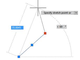
When moving the cursor to the grip of preselected objects, the dimension values associated with it are dynamically displayed on the screen. When moving the cursor to the grip belonging to several selected objects, the dimensions of each object associated with this grip will be displayed.
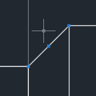
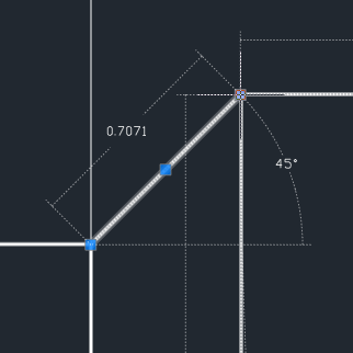
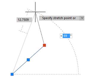
When selecting the object grip, the values of dynamically displayed dimensions become available for editing. By pressing TAB key, move to the desired value. Enter a new value from the keyboard.
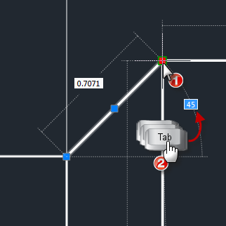
To move to the next dimension value, press TAB. The edited dimension will fix its value, and the lock icon will be displayed in its right part.
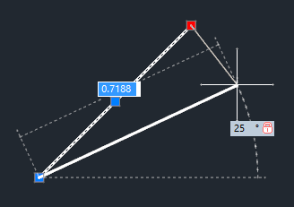
To complete the editing, press ENTER.
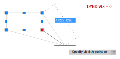
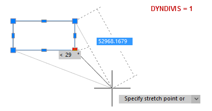
Not all dynamic dimensions can be seen on the screen simultaneously. The number of simultaneously displayed dimensions is controlled by the DYNDIVIS variable. Depending on its value, the following can be displayed simultaneously:
· only one dimension (DYNDIVIS = 0):
· only two dimensions (= 1):
· or all dimensions (= 2):
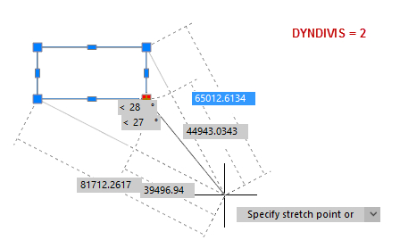
If only one or two dimensions are displayed simultaneously, and you need to display others, this can be done by cyclically pressing the Tab key. Press Tab until the desired dimensions are visible. On subsequent cursor movement, the selected dimensions will continue to be displayed.
|
|
|
|
|
|
When a point is requested by a command, you can enter its coordinates in the tooltip box near the crosshair, where the current cursor coordinates are shown. By toggling the TAB key, switch to necessary value to edit it from the keyboard. Press ENTER when done.
Entering coordinates with dynamic dimensions mode on
If, in addition to the mouse dynamic input, the dynamic dimensions mode is enabled, then while entering the second and subsequent points of the object being created, the coordinate field is not displayed explicitly.
In this case, do not be embarrassed, just start entering the point coordinates using the keyboard: enter the coordinate along the X axis, enter a comma and continue entering coordinates along the remaining axes, separated by commas. For example: 12045,-430.07,0.005 Or -45,28
The value being entered will first display in the field of one of the dynamic dimensions.
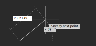
After entering the first comma, the coordinate fields begin to be displayed explicitly near the cursor.
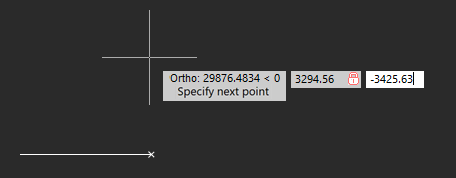
By pressing the TAB key, you can move to the desired value to edit it from the keyboard. When finished entering, press ENTER.
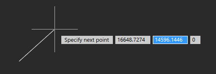
When switching between fields using TAB, the direction of the base (zero) angle is assumed to be East, Counterclockwise, regardless of what is specified in the Drawing Units (UNITS) dialog.
For example, when entering like: 300TAB30, where 300 is the length, 30 is the angle, the base angle will always be East, counting Counterclockwise.
The direction of the base angle specified in the Drawing Units dialog will be taken into account for the following input options:
@300TAB30
@300<30
300<30
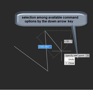
Dynamic prompts provide an alternative way to enter command parameter values. In the tooltip field near the cursor, requests and prompts of the active command appear, necessary to complete the command. Data can be entered in the dynamic prompt fields instead of the command line. You can enter command keywords and requested numeric values.
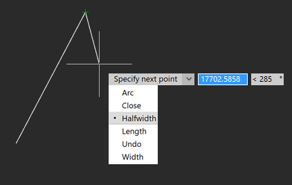
The list of available values and options can be expanded by pressing the DOWN ARROW key on the keyboard. Then choose the desired value with an ARROW keys and press ENTER.
|
|
|


 De
De  Es
Es  Fr
Fr  Pt
Pt 

