

 De
De  Es
Es  Fr
Fr  Pt
Pt 

-
-
-
-
-
-
-
-
-
-
-
-
-
Drawing Units
-
-
-
-
-
-
-
-
-
-
-
-
-
-
-
-
-
-
-
-
-
-
-
-
-
-
-
-
-
-
-
-
-
-
-
-
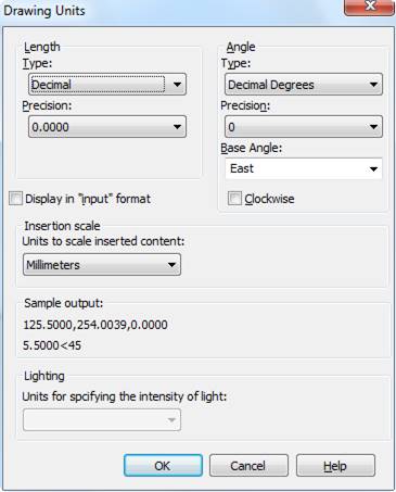
Drawing Units
 Ribbon: Home – Properties >
  Units
Units
Menu: Format – Units…
 Command line: UNITS, UN
The command opens the Drawing Units dialog box, where you can define the format and accuracy of the linear and angle units.
By default, the base direction to measure angles is to the right of the initial point (East). Angles should be measured in a counter clockwise direction to give positive numbers.
Parameters:
Linear
|
Type: |
Current format of linear units. Available formats in the drop-down list: · Architectural · Decimal · Engineering · Fractional · Scientific |
|
Precision: |
Accuracy of current linear units. |
Angle
|
Type: |
Current format of angle units. Available formats in the drop-down list: · Deg/Min/SEC · Grads · Decimal degrees · Radians · Surveyor’s units |
|
Precision: |
Accuracy of current angle units. |
|
Base Angle: |
Direction of base angle. Available formats in the drop-down list: · East · North · West · South · Pick angle – by specifying two points in the graphic area. |
|
Clockwise |
To change positive direction to measure angles to clockwise. |
|
Display in “input” format |
Enables/disables display of drawing units without spaces. |
Insertion scale
|
Units to scale inserted content: |
Units to measure blocks and external references, inserted in a document. If a block or inserted document was created with units which do not coincide with the units set in this section, the block or inserted document will be scaled to the specified units. Scale is defined by the ratio of units in an inserted document and a current document. If the Undefined option is selected, the insertion is performed without scaling. |
|
Sample output |
Preview of current linear and angle units set in the dialog box. |
Lighting
|
Units for specifying the intensity of light: |
Selecting light intensity units and lighting type. The following options are available in the drop-down list: · Generic – standard lighting is included without lighting fixtures, lighting intensity units are not used (system variable LIGHTINGUNITS = 0); · American – photometric lighting is included, American units of lighting intensity are used - Foot-candle (LIGHTINGUNITS = 1); · International – photometric lighting is included, the lighting intensity units of the International System of Units (SI) are used - Lux (LIGHTINGUNITS = 2, default value). |
Non-dialog Mode of the Unit Command
Command line: -UNITS
Setting the format and precision of drawing units using the command line.
Command option:
|
Report formats: (Examples) 1. Scientific 1.55E+01 2. Decimal 15.50 3. Engineering 1'-3.50" 4. Architectural 1'-3 1/2" 5. Fractional 15 ½ With the exception of Engineering and Architectural formats, these formats can be used with any basic unit of measurement. For example, Decimal mode is perfect for metric units as well as decimal English units. |
List of available formats for linear units. |
|
Enter choice, 1 to 5 <2>: |
Select the unit format (sequence number from the list above). Press ENTER to finish selection. |
|
Enter number of digits to right of decimal point (0 to 8) <4>: |
Set the precision of linear units. Press ENTER to finish selection. |
|
Systems of angle measures: (Examples) 1. Decimal degrees 45.0000 2. Degrees/minutes/seconds 45d0'0" 3. Grads 50.0000g 4. Radians 0.7854r 5. Surveyor's units N 45d0'0" E |
List of available formats for angular units. |
|
Enter choice, 1 to 5 <1>: |
Select the unit format (sequence number from the list above). Press ENTER to finish selection. |
|
Enter number of fractional places for display of angles (0 to 8) <0>: |
Set the precision of angular units. Press ENTER to finish selection. |
|
Direction for angle 90: East 3 o’clock = 0 North 12 o’clock = 90 West 9 o’clock = 180 South 6 o’clock = 270 |
List of directions of the base (zero) angle. |
|
Enter direction for angle 90 <0>: |
Select the direction of the base (zero) angle (sequence number from the list above). Press ENTER to finish selection. |
|
Measure angles clockwise? [Yes/No]? <N>: |
Select positive angle counting clockwise or counterclockwise |