De
De  Es
Es  Fr
Fr  Pt
Pt 

-
-
-
-
-
-
-
-
-
-
-
-
-
-
-
-
-
-
-
-
-
-
-
-
-
-
-
-
-
-
Dimensions Editing
-
-
-
-
-
-
-
-
-
-
-
-
-
-
-
-
-
-
-
-
-
-
-
-
-
-
Dimensions Editing
Dimensions are edited in the Properties bar and in the Edit dimension dialog box.
Editing Dimensions in the Properties Bar
Value – dimension value.
Prefix – text before the value.
Symbol – drop-down list to select a symbol before the value.
Suffix – text after the value.
Text under – text under the dimension shelf.
Real value – read-only, Yes by default.
Automatically control the measurement scale in the viewport – the property is available only in layouts. This property controls the influence of the style measurement scale. Yes – changing the style measurement scale value affects the dimension measurement scale. No – changing the style measurement scale value does NOT affect the dimension measurement scale. When changing the measurement scale from outside, the property will be automatically reset, i.e. the value will become No.
Editing Dimensions Using Grips
Editing with grips is the fastest and most efficient way to change dimensions, since manipulations are performed with the mouse cursor, which minimizes access to menus and toolbars.
By default, the Stretch (GRIP_STRETCH) mode is set for editing dimensions with grips.
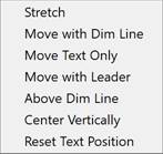
Dimensions have multifunctional grips for text and arrows. A dynamic menu of editing modes appears when you hover over a grip:

For the selected grip, it is possible to cycle through the parameters by pressing the CTRL key. Items in the dynamic menu can be selected either with the mouse cursor or with the UP ARROW / DOWN ARROW keys on the keyboard.
Grip settings are performed in the Handles section of the OPTIONS dialog.
To edit a dimension using multi-purpose grips:
1. Select the dimension.
2. Select the multi-purpose grip and press the CTRL key to select an editing option. Or move the cursor over the multi-purpose grip, open the dynamic menu and select an editing option from the dynamic menu.
3. Move the cursor to dynamically display the change to the object.
4. Left-click to fix the change.
 Text editing grip
Stretch – stretches the dimension (further or closer to the object). The Base point, Copy options are available in the command line, as for regular grips.
Move with Dim Line – moves text and dimension line.
Move Text Only – moves text to any place in the drawing without changing the dimension line position.

Move with Leader – places text on the leader.

Above Dim Line – places text above the dimension line (or to the left of the dimension line for vertical dimensions)

Center Vertically places the center of the text on the dimension line.

Reset Text Position – places text in the default position (for the current dimension style).
Arrow editing grip
Stretch – stretches the dimension (further or closer to the object). The command line has the same command options as for regular grips.
Chain – creates a chain of dimensions, where each subsequent dimension starts from the end point of the previous one. The DIMCONTINUE command options are available in the command line.
Baseline – creates basic dimensions, where each subsequent dimension is measured from a common starting point. The DIMBASELINE command options are available in the command line.
Flip Arrow – changes the arrow direction.
Editing a Dimension in the Edit Dimension Dialog
 Context menu of the dimension:
  Edit
Edit
By right-clicking on the dimension (the dimension is highlighted in green) or double-clicking the left mouse button on the dimension (the Dimensions parameter should be set to Yes in the Settings nanoCAD (PARAMS) dialog, on the Main Options tab, in the Edit section – By Double-click)
 Command line: EDIT, FEDIT
The Edit dimension dialog box:
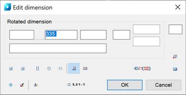 The window is divided into an area of text input fields with the name of the size type and a set of size formatting commands.
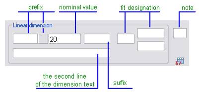
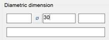
The structure of the input fields for the dimension text:
Text Fields:
|
Parameter |
Description |
|
Dimension type: |
Name of the dimension type (for example, Linear dimension, Diameter dimension, Angular dimension etc.). |
|
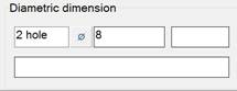
Prefix: |
The prefix consists of the text input field and the Symbol button. If the dimension does not have a special symbol that is set as the default prefix, the button is displayed without an image:
If a special symbol from the panel is set by default, it appears on the button:
A prefix specified in the Edit dimension dialog box has precedence over a prefix set by default. Example of dimension text with a prefix consisting of the text and special symbol:
|
|
Nominal value: |
Field to display and edit the nominal value of the dimension text. |
|
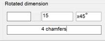
Suffix: |
This field displays the suffix of the dimension text set by default, such as the chamfer angle designation:
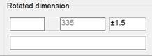
In the same field, you can set the value of a custom symmetrical fit of the dimension:
|
|
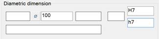
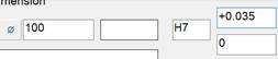
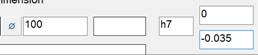
Fit designation: |
The fields display the specified fit values of the dimension. Depending on the way the fits are written (the Fit view button), the values in the fields can be displayed in different ways:
|
|
Note: |
The input field for a note for the dimension is used to create the hyperlink to the item that contains the technical conditions that define the general requirements for several dimensions. For example, in this field you can type the star symbol (*) to denote the reference dimension (having the corresponding item in the technical conditions). |
|
The second line of the dimension text: |
An example displaying the dimension text consisting of two lines:
|
 . Click the icon to open the panel to select a symbol:
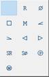
Buttons
|
Button |
Description |
|
|
First arrow and Second arrow allow you to select the arrow type. Click to open the panel and select the required arrow type:
|
|
|
These buttons are used to turn on/off the modes for placing text in the Square, Round or Pointed brackets. |
|
|
The Text on leader button switches the mode for displaying the text on the leader. Example: Mode is on Mode is off
|
|
|
Text in rectangle button is used to switch the mode for displaying the dimension text in a rectangle. |
|
|
Use this button to choose the method of writing the fit. Click to open the following panel:
|
|
|
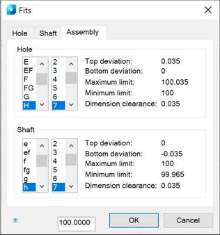
The Fit table button opens the Fits dialog. |
|
|
The Calculate value button opens the calculator to calculate values. |
|
|
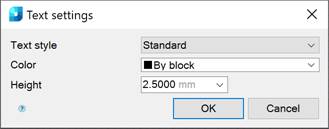
This button opens the Text settings dialog box to change the style, height and color of the dimension text. |
|
|
The Match Properties button temporarily closes the Edit dimension dialog box to select the dimension whose properties should be copied to the editable dimension. |
|
|
The Text Style button opens the Text settings dialog box.
Text style – drop-down list for selecting a text style. Color – drop-down list for selecting a text color. Height – drop-down list for selecting character height. It’s possible to enter values from the keyboard. |


Right-clicking in an input field opens a context menu with additional commands. The presence of a particular command in the context menu depends on the purpose of the field.

To set the dimension fit:
1. Click the button  .
.
2. In the panel that appears, select the method of writing the tolerances:
3. Click the button  .
.
4. In the opened Fits dialog box, select the required values: