

 De
De  Es
Es  Fr
Fr  Pt
Pt 

-
-
-
-
-
-
-
-
-
-
-
-
-
-
-
-
-
-
-
-
-
-
-
-
-
-
-
-
-
-
-
-
-
-
-
-
-
-
-
-
-
-
-
-
-
-
-
-
-
Design pinion shafts
-
-
-
-
-
-
-
-
-
-
-
-
-
-
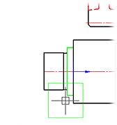
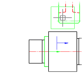
Design pinion shafts
In the dialog box, select the folder Editing shaft gears and select a template cylindrical gear shaft.
After selecting the parts "cylindrical gear shaft" mouse pointer is displayed as a standard cross-hair, blue arrows and the image of a small green square (standard view). When you hover the pointer on the shaft, this area will be highlighted in green and contains the insertion point of the ring gear.
In the dialog box, spur gear option
Take the rate you need to click on the drop-down list of the calculations and indicate which item you want to transfer
render (or gear wheel).
The option is available if a calculation has been created. To insert an object into a chain of objects, click OK. After applying the gear, the cursor pointer takes the standard form. It is further proposed to continue drawing the next part of the engagement.
Drawing on the results of the calculation of gearing
Original drawing:
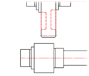
Double click the left mouse button on the axis of the shaft, call the dialog box Editing shaft.
Tab gears.
Select a template cylindrical gear shaft.
By clicking the left mouse button, set the insertion point on the lower shaft gear.
Move the cursor pointer to the wheel on the upper shaft (ring gear is highlighted in green). Left-click to confirm your choice.
In the drop-down list of the calculations, specify the desired (in our example - calculation with the name of "Example of calculation") and select what should render the lower portion of the shaft (in this example - "Gear").
Click the OK button. At the request of the "Insert object in the chain of objects?" Answer "yes".
Press ESC to finish drawing commands engage and close the dialog box.
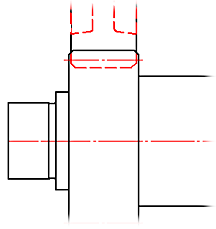
As a result, the drawing rendered pair of gearing with deposited assembly dependencies.